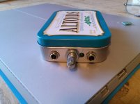
Heres the "rough" holes...I will file and de-burnish the holes and paint the area black to hide the imperfections. I had one slip and a small scratch when drilling the small led hole a real pain...But when its done it will look great.
I will post when all done powered up so you can see the led.
It took a good hour to do these holes.
First was the pot with paint inside and small center punch and start with small drill and work up to the hole size, larger drill size will catch and rip the thin tin material so have to be very slow and methodical and use round file to massage hole.
The same for the two 3.5mm jacks. The led was last.
Alex
Attachments
From back in post #21:
Uh, yeah. I wondering about leaving the 47 pF cap out myself. But my understanding is that there's no point putting it in unless there's some feedback resistance in parallel. Which means the gain would have to be > 1x, though it could be "close". I might be wrong on that.
Good point, in fact I've just made a new BOM revision to include some choices for the gain resistors. Attached below and also out at the project Google Drive link. I've grouped the resistor choices a bit better for 3 typical voltage gains: 1x, 2x, and 4x.
For 1x the standard thing to do is jumper the feedback resistors R11 & R12 (jumper wires instead of resistors for those pads) and then no need to install the 47pF caps C7 & C8. R8 & R9 are left unpopulated.
I'm just curous about johnc124's take on it given that he posted in the vendor forum thread that he did a bit of testing to settle on the 47pF for maximum stability with larger capacitive loads. Pretty slick being able to converse with someone who worked on the design of the chip.")
Uh, yeah. I wondering about leaving the 47 pF cap out myself. But my understanding is that there's no point putting it in unless there's some feedback resistance in parallel. Which means the gain would have to be > 1x, though it could be "close". I might be wrong on that.
Uh, yeah. I wondering about leaving the 47 pF cap out myself. But my understanding is that there's no point putting it in unless there's some feedback resistance in parallel. Which means the gain would have to be > 1x, though it could be "close". I might be wrong on that.
You are right! The compensation capacitor forms a filter along with the feedback resistance. The OPA1688 datasheet doesn't have the writeup on it, but the OPA1622 datasheet does on page 24, for the case of balanced inputs from a DAC:
"Capacitors C1 and C2 limit the bandwidth of the circuit to prevent the unnecessary amplification of interfering signals. The maximum value of these capacitors is determined by the limitations on frequency response magnitude deviation detailed in the Design Requirements section. C1 and C2 combine with resistors R2 and R4 toform a pole, as shown in Equation 9:"
fp = 1 / [2*pi*(R2,R4)(C1,C2)]
referring to figure 52 in that datasheet, which is similar to figure 49 in the OPA1688 datasheet. From the discussions in the Vendor forum johnc124 said he had to abandon using the network as an RF filter with the OPA1688, due to the need to keep the cap smaller for stability with capacitive loads. That is why the capacitor is 470pF for the OPA1622, but only 47pF for the OPA1688. Lol, I had to ask about that because I was sure it had to be a typo at first.
So that is why I've included the RF filter on the front of the CMOY.So long story short - I agree, with the feedback resistor jumpered to make a voltage follower there wouldn't be any need for that 47pF cap at all.
LED options
Seeing Alex's photo in post #41 above reminds me that I need to add a few words in the build instructions about options in using the "power on" LED.
The mint tin CMOYs I'm seeing out on eBay don't appear to have "power on" LEDs. I added one because I was able to do it in a rather clever fashion. The LED is in series with the two solid state relay internal LEDs, a current source, the on/off switch and the comparator output which grounds the whole thing. As luck would have it there was enough voltage available, even at the minimum 7.0Vdc/cell cut-off, to power all those LEDs and the current source.
This means that the LED's energy comes for "free" - it is the current already flowing though that control circuit. Just a bit less for the current source to do. I couldn't pass that up. I was able to wedge the LED in on the front between the pot and input jack, but as Alex' photo shows it is mighty close to the nut for the pot if brought through the panel.
So what I did was make 2 pad positions for the LED, a forward position and one slightly behind it. In the forward position it will stick through the panel as in Alex' build. In the rear position it will clear the panel and instead you can just make a small drill hole to let the light out. That is what I've been doing in my builds so far, using the rear position.
A third option is using a LED with wires attached mounted somewhere else, such as the front or back sides of the mint tin, that solders into one pair of the LED holes. A good choice is Mouser part #645-558-0201-003F for $2.18. That is a panel-mount 3mm green LED already in a plastic holder with wire leads attached. Just drill a 4mm hole, insert the LED, glue it from behind the panel, and solder those leads onto the CMOY LED holes.
And a fourth option just don't use the LED at all. Since there is a current source in series with it all you can simply use a jumper wire to jumper across one set of the LED pads. You do need to jumper it though. Leaving the LED out without jumpering will break the circuit and the CMOY would never turn on.
Seeing Alex's photo in post #41 above reminds me that I need to add a few words in the build instructions about options in using the "power on" LED.
The mint tin CMOYs I'm seeing out on eBay don't appear to have "power on" LEDs. I added one because I was able to do it in a rather clever fashion.
The LED is in series with the two solid state relay internal LEDs, a current source, the on/off switch and the comparator output which grounds the whole thing. As luck would have it there was enough voltage available, even at the minimum 7.0Vdc/cell cut-off, to power all those LEDs and the current source.This means that the LED's energy comes for "free" - it is the current already flowing though that control circuit. Just a bit less for the current source to do. I couldn't pass that up. I was able to wedge the LED in on the front between the pot and input jack, but as Alex' photo shows it is mighty close to the nut for the pot if brought through the panel.
So what I did was make 2 pad positions for the LED, a forward position and one slightly behind it. In the forward position it will stick through the panel as in Alex' build. In the rear position it will clear the panel and instead you can just make a small drill hole to let the light out. That is what I've been doing in my builds so far, using the rear position.
A third option is using a LED with wires attached mounted somewhere else, such as the front or back sides of the mint tin, that solders into one pair of the LED holes. A good choice is Mouser part #645-558-0201-003F for $2.18. That is a panel-mount 3mm green LED already in a plastic holder with wire leads attached. Just drill a 4mm hole, insert the LED, glue it from behind the panel, and solder those leads onto the CMOY LED holes.
And a fourth option just don't use the LED at all. Since there is a current source in series with it all you can simply use a jumper wire to jumper across one set of the LED pads. You do need to jumper it though. Leaving the LED out without jumpering will break the circuit and the CMOY would never turn on.
Last edited:
Build instructions!
I've made it through a first pass of the build instructions for the Super CMOY. More to come, but this should be enough for folks to get their board built and tested. Attached below and also posted now out at the project's Google Drive link.
I've made it through a first pass of the build instructions for the Super CMOY. More to come, but this should be enough for folks to get their board built and tested. Attached below and also posted now out at the project's Google Drive link.
Attachments
If you put a basic schematic up here I can do some stability checks to confirm the value of the capacitor. The basic concept is to just put a slight dip in the 1/Beta (inverse of the feedback signal) right around the 0dB loop gain point, which gives a little boost in phase margin. Maybe I'll have some free time on a trans-pacific flight to look at it!
Revised schematic posted
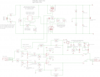
Thank you! Any input is appreciated. The schematic is posted below in .png and pdf, and also updated at the project Google drive link:
https://drive.google.com/folderview?id=0B67cJELZW-i8b0VRa29ScjFac2M&usp=sharing
then V4.0 -> schematic.
Good timing too, I was about to post an updated schematic. Most of what has changed on the schematic are just cleaninig up the part labels. I believe everything has the manufacturer part number now, but if anyone finds a missing number, label, or value please let me know.
I've swapped the 1N5818 Schottky battery polarity protection diodes for SB140s. Similar thing, the SB140s just offer a bit more for the money.
And as per post #39 and johnc124's input the voltage gain resistor set for the "standard" 2x case shown on the schematic are 825 ohms. The BOM lists the alternate resistor sets for 3x and 4x gain.
If you put a basic schematic up here I can do some stability checks to confirm the value of the capacitor.
Thank you! Any input is appreciated.
The schematic is posted below in .png and pdf, and also updated at the project Google drive link:https://drive.google.com/folderview?id=0B67cJELZW-i8b0VRa29ScjFac2M&usp=sharing
then V4.0 -> schematic.
Good timing too, I was about to post an updated schematic. Most of what has changed on the schematic are just cleaninig up the part labels. I believe everything has the manufacturer part number now, but if anyone finds a missing number, label, or value please let me know.
I've swapped the 1N5818 Schottky battery polarity protection diodes for SB140s. Similar thing, the SB140s just offer a bit more for the money.
And as per post #39 and johnc124's input the voltage gain resistor set for the "standard" 2x case shown on the schematic are 825 ohms. The BOM lists the alternate resistor sets for 3x and 4x gain.
Attachments
Last edited:
You are right! The compensation capacitor forms a filter along with the feedback resistance. The OPA1688 datasheet doesn't have the writeup on it, but the OPA1622 datasheet does on page 24, for the case of balanced inputs from a DAC:
"Capacitors C1 and C2 limit the bandwidth of the circuit to prevent the unnecessary amplification of interfering signals. The maximum value of these capacitors is determined by the limitations on frequency response magnitude deviation detailed in the Design Requirements section. C1 and C2 combine with resistors R2 and R4 toform a pole, as shown in Equation 9:"
fp = 1 / [2*pi*(R2,R4)(C1,C2)]
referring to figure 52 in that datasheet, which is similar to figure 49 in the OPA1688 datasheet. From the discussions in the Vendor forum johnc124 said he had to abandon using the network as an RF filter with the OPA1688, due to the need to keep the cap smaller for stability with capacitive loads. That is why the capacitor is 470pF for the OPA1622, but only 47pF for the OPA1688. Lol, I had to ask about that because I was sure it had to be a typo at first.
So long story short - I agree, with the feedback resistor jumpered to make a voltage follower there wouldn't be any need for that 47pF cap at all.
Um, I think I probably didn't say that right. My take was maybe it would be better to have that 47 pF cap and a very low gain rather than no cap and a gain of 1x. I was working under the impression that the cap is highly recommended for stability. I'll leave it to the experts though.
For a quick-and-dirty simulation I used a 400pF capacitor as a worst case headphone load. In the gain of 2 case (825 / 825 resistors) I get 50 degrees of phase margin with the 47pF feedback capacitor and 35 degrees without it. I'd recommend you keep it.
Nice!
50 degrees is a healthy amout of margin. I know folks usually consider 20 to 30 degrees the edge.Lucien has a really good related question above. What happens to phase margin with the same 400pF Cload in the unity gain case, with the output wired to inverting input with no compensation capacitor? Like Lucien says, would it be better to maintain some small amount of gain, like 1.25x, to keep the comp capacitor for stability? I suspect that unit gain current buffers, or near unity gain, are gong to be a popular configuration for the Super CMOY.
And another OPA1688 question, if you get some time on your plane ride back.
I see the impedances looking out the chip inputs are terrifically unbalanced. 49.9K on non inverting and 825 | 825 = 412 on the other at DC. With bipolar inputs normally it would be best to keep those roughly equal of course, so the input bias current IR drops are equal and cancel. Here I know we have FET input with minimum Ib, but... will the imbalance in input Z matter for anything other than a slight addition to DC output offset? As for input impedance distortion, that should be more the series resistance, if I'm looking at things right, which would be worst at pot mid-point of 5K | 5K = 2.5K, which shouldn't be a problem. Usually those input distortion curves start about there if I'm remembering right.Thanks for your input!
If I did it again I dont think I would put the led next to the vol pot....with the knob on it the led will be partially blocked. I like the idea of having the led in another place and just wire to it.
Alex
Yep, I agree, on seeing your photo I realized that LED in the forward position, through the panel, isn't really going to work. Pretty much needs to either be in the rear position with a small panel hole, or moved somewhere else entirely on leads. Or left off and just jumpered.
Revised BOM - 3x and 4x gain resistors (again)
I realized last night that I went in the wrong direction for the new 3x and 4x gain resistor sets in the revised BOM yesterday. I increased the feedback resistor to 1.65K and 2.49K, when instead I should have left the feedback resistor constant at the 825R and decreased the resistor from inverting-to-ground to 412R and 274R. So here is a BOM with that change, also posted out on the project Google Drive link.
The smallest resistance load the feedback network would present to the OPA1688 chip output is now 825R + 274R = 1099R. By way of comparison, with NwAvGuy's O2 headamp, the largest load was (for 6.5x gain) 1.5K + 274R = 1774R. That was applied to the O2's NJM2068 chip though which is only THD specified down to 2K. With the OPA1688 we are good to 16 ohms!
Attachments
Last edited:
Ok as the old movie adage goes "Its Alive!!".
Got the diodes and battery terminals and it worked first time.
Totally quiet, no turn on or off thumps. Gain set to 2X.
I disconnected the batteries one at a time and it turned off quickly ans silently no thumps or noise. Great!! This means that wonderful tiny chip that is so swell to solder got soldered in ok fine!! LOL.
I will finish up with the cosmetic stuff and post some pix when done in a few days! Just want to listen for awhile and make some comparisons.
Alex
Thanks AGDR for a wonderful Super Cmoy!!!!
and
Thanks to TI for that little OPA 1688!
Hole cutting template for the mint tin - holes up 2mm now - molded 9V snaps
Excellent!! That power management circuit took a lot of work, but it was worth it. Good work with your testing, having it thump-free even when a battery got disconnected was a big goal. Without the battery cutoff PM circuit and headphone relay circuit there was a significant amount of DC at the amp output when one power rail suddenly went away. NwAvGuy gets the credit for the core PM circuit of course, I just updated it with some new parts after having thought about it for 4 years.
Some new stuff -
Hole cutting template for the mint tin and CMOY PCB now 2mm up from mint tin bottom
I've posted a .pdf hole cutting template below, and out at the project Google Drive link, for the front of the mint tin to make things a little easier. When you print make sure you have "actual size" selected on the PDF print dialog so your PC doesn't try to scale it.
The reference point is the centerline mark at the top. Measure to find the center line of your front panel (mint tin width / 2 of course), mark it, then line it up with the template mark. Note that the pot is just slightly off from the centerline, I had to do that to get the LED to fit. The bottom of the template sits on the table along with the bottom of the can. I have centering marks around the holes, in case you want to cut them out to trace around them. You can still find the middle of the hole on the panel metal.
One important change! In the process of doing this I discovered the Super CMOY can't sit directly on top of the 3.5mm jacks, as I had originally intended, or the knob will hit the table first when it is installed. The board needs to be mounted such that about 2mm of additional space is between the bottom of the case and the top of the inverted 3.5mm jacks.
I've added the extra 2.0mm to the template, so if you use it you automatically get the right height. I'm going to look around for some 2mm thick tape that could be stuck on top of the 3.5mm jacks too. Scotch double-stick "mounting tape" at the stores is apparently 3mm, just a bit too thick. There is no requirement to put something in the 2mm gap between the bottom of the can and the top of the inverted 3.5mm jacks, the nuts on the front panel parts will hold the PC board just fine.
Rigid molded 9V battery snaps
Another discovery today, I received some of the rigid molded Keystone 235-M battery connectors (Mouser 534-235-M) and they fit. The molded version will be a bit more rugged than the vinyl covered Keystone 235 I've been using. I'm going to list teh 235-M as an alternate in the BOM. The batteries just exactly fit with the molded battery snaps (plenty of space with the vinyl snaps), and that is using the Powerex 300mAhr NiMH "9V" which is just a tad wider than most 9V battery. Worst case you may have to slightly file down one corner of the outer molded battery snap if your particular batteries are a bit wider.
BOM
Lol, another BOM revision for the battery snaps. Going forward I'm just going to say "check the Google Drive link for the most current BOM", until it gets stable then I'll post it here again.
Ok as the old movie adage goes "Its Alive!!".
Excellent!!
That power management circuit took a lot of work, but it was worth it. Good work with your testing, having it thump-free even when a battery got disconnected was a big goal. Without the battery cutoff PM circuit and headphone relay circuit there was a significant amount of DC at the amp output when one power rail suddenly went away. NwAvGuy gets the credit for the core PM circuit of course, I just updated it with some new parts after having thought about it for 4 years. Some new stuff -
Hole cutting template for the mint tin and CMOY PCB now 2mm up from mint tin bottom
I've posted a .pdf hole cutting template below, and out at the project Google Drive link, for the front of the mint tin to make things a little easier. When you print make sure you have "actual size" selected on the PDF print dialog so your PC doesn't try to scale it.
The reference point is the centerline mark at the top. Measure to find the center line of your front panel (mint tin width / 2 of course), mark it, then line it up with the template mark. Note that the pot is just slightly off from the centerline, I had to do that to get the LED to fit. The bottom of the template sits on the table along with the bottom of the can. I have centering marks around the holes, in case you want to cut them out to trace around them. You can still find the middle of the hole on the panel metal.
One important change! In the process of doing this I discovered the Super CMOY can't sit directly on top of the 3.5mm jacks, as I had originally intended, or the knob will hit the table first when it is installed. The board needs to be mounted such that about 2mm of additional space is between the bottom of the case and the top of the inverted 3.5mm jacks.
I've added the extra 2.0mm to the template, so if you use it you automatically get the right height. I'm going to look around for some 2mm thick tape that could be stuck on top of the 3.5mm jacks too. Scotch double-stick "mounting tape" at the stores is apparently 3mm, just a bit too thick. There is no requirement to put something in the 2mm gap between the bottom of the can and the top of the inverted 3.5mm jacks, the nuts on the front panel parts will hold the PC board just fine.
Rigid molded 9V battery snaps
Another discovery today, I received some of the rigid molded Keystone 235-M battery connectors (Mouser 534-235-M) and they fit. The molded version will be a bit more rugged than the vinyl covered Keystone 235 I've been using. I'm going to list teh 235-M as an alternate in the BOM. The batteries just exactly fit with the molded battery snaps (plenty of space with the vinyl snaps), and that is using the Powerex 300mAhr NiMH "9V" which is just a tad wider than most 9V battery. Worst case you may have to slightly file down one corner of the outer molded battery snap if your particular batteries are a bit wider.
BOM
Lol, another BOM revision for the battery snaps. Going forward I'm just going to say "check the Google Drive link for the most current BOM", until it gets stable then I'll post it here again.
Attachments
Last edited:
Neat project! Are boards currently available?
Definitely looks like a fun little weekend project, plus cmoys are fantastic overall.
Boards are available, at-cost for forum members! All the details are here:
http://www.diyaudio.com/forums/vendors-bazaar/293309-agdr-audio-sales-thread.html
Boards are available, at-cost for forum members! All the details are here:
http://www.diyaudio.com/forums/vendors-bazaar/293309-agdr-audio-sales-thread.html
My mistake, must have missed the link earlier in the thread.
PM sent!
"9V" battery internal resistance shootout: NiMH, lithium, primary - part 1
I had a few minutes so I went ahead and did the "9V" battery internal resistance test discussed in posts above. The results are shocking! Pun intended, but they really are!
Photos:
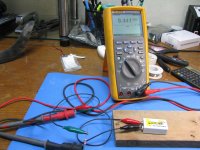
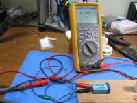
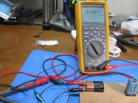
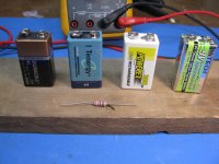
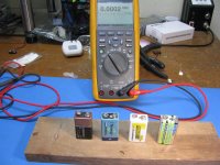
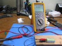
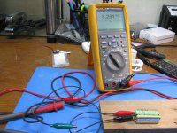
* First 3 are the test setup. All the rechargeable batteries here are about 1 hour fresh of their various battery-manufacturer chargers. The primary cell is new right out of the package.
The test candidates are a primary (throw-away) 9V battery, a Tenergy brand "9V" (8.4Vdc nominal 7-cell) 250mAhr NiMH rechargeable battery (same one used in the NwAvGuy O2 headphone amplifier), a maha Powerex brand "9V" (8.4Vdc nominal 7-cell) 300mAhr NiMH rechargeable battery, and a HiTech brand "9V" (7.4Vdc nominal 2-cell) 720mAhr lithium polymer battery. The last 2 are the ones I've linked to in some posts above as recommended. I also have a couple of the maha Powerex 9.6Vdc 230mAhr batterys around here somewhere, but couldn't put my hands on them tonight.
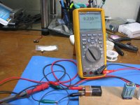
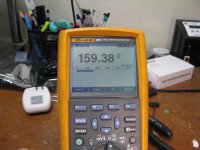
* Next photo is measuring the resistor in the photos above, a 160 ohm 3W, which measures 159.4 ohms
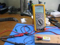
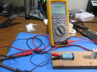
* Next three are measuring the 9V primary battery. The middle photo is why there is a tail in some of the pictures. The open circuit voltage is 9.57Vdc, the voltage under load is 9.24Vdc. The current through the series setup is 9.24/159.4 = 58mA. The voltage across the internal battery resistance is 9.57 - 9.24 = 0.33Vdc. The internal resistance of the primary battery is 0.33Vdc/58mA = 5.69 ohms. About 5x the amount I always had assumed that primary 9V cells had!
* Next two are measuring the Tenergy brand 8.4V nominal NiMH rechargeable 7-cell battery. The open circuit voltage is 9.39Vdc, the voltage under load is 9.24Vdc (again! strange). The current through the series setup is 9.24/159.4 = 58mA. The voltage across the internal battery resistance is 9.39 - 9.24 = 0.15Vdc. The internal resistance of this rechargeable battery is 0.15Vdc/58mA = 2.59 ohms. About half that of the primary 9V battery.
* Next two are measuring the maha Powerex brand 8.4V nominal NiMH rechargeable 7-cell battery. The open circuit voltage is 9.57Vdc, the voltage under load is 9.44Vdc. The current through the series setup is 9.44/159.4 = 59mA. The voltage across the internal battery resistance is 9.57 - 9.44 = 0.13Vdc. The internal resistance of this rechargeable battery is 0.13Vdc/59mA = 2.20 ohms. Slightly less than the Tenergy version, but still pretty close, which they should be since they are the same NiMH technology. Makes a good double-check on the procedure.
I'm out of photo slots, so part 2 next. That one is the "shocker", the lithium battery!
I had a few minutes so I went ahead and did the "9V" battery internal resistance test discussed in posts above. The results are shocking!
Pun intended, but they really are!Photos:
* First 3 are the test setup. All the rechargeable batteries here are about 1 hour fresh of their various battery-manufacturer chargers. The primary cell is new right out of the package.
The test candidates are a primary (throw-away) 9V battery, a Tenergy brand "9V" (8.4Vdc nominal 7-cell) 250mAhr NiMH rechargeable battery (same one used in the NwAvGuy O2 headphone amplifier), a maha Powerex brand "9V" (8.4Vdc nominal 7-cell) 300mAhr NiMH rechargeable battery, and a HiTech brand "9V" (7.4Vdc nominal 2-cell) 720mAhr lithium polymer battery. The last 2 are the ones I've linked to in some posts above as recommended. I also have a couple of the maha Powerex 9.6Vdc 230mAhr batterys around here somewhere, but couldn't put my hands on them tonight.
* Next photo is measuring the resistor in the photos above, a 160 ohm 3W, which measures 159.4 ohms
* Next three are measuring the 9V primary battery. The middle photo is why there is a tail in some of the pictures.
The open circuit voltage is 9.57Vdc, the voltage under load is 9.24Vdc. The current through the series setup is 9.24/159.4 = 58mA. The voltage across the internal battery resistance is 9.57 - 9.24 = 0.33Vdc. The internal resistance of the primary battery is 0.33Vdc/58mA = 5.69 ohms. About 5x the amount I always had assumed that primary 9V cells had! * Next two are measuring the Tenergy brand 8.4V nominal NiMH rechargeable 7-cell battery. The open circuit voltage is 9.39Vdc, the voltage under load is 9.24Vdc (again! strange). The current through the series setup is 9.24/159.4 = 58mA. The voltage across the internal battery resistance is 9.39 - 9.24 = 0.15Vdc. The internal resistance of this rechargeable battery is 0.15Vdc/58mA = 2.59 ohms. About half that of the primary 9V battery.
* Next two are measuring the maha Powerex brand 8.4V nominal NiMH rechargeable 7-cell battery. The open circuit voltage is 9.57Vdc, the voltage under load is 9.44Vdc. The current through the series setup is 9.44/159.4 = 59mA. The voltage across the internal battery resistance is 9.57 - 9.44 = 0.13Vdc. The internal resistance of this rechargeable battery is 0.13Vdc/59mA = 2.20 ohms. Slightly less than the Tenergy version, but still pretty close, which they should be since they are the same NiMH technology. Makes a good double-check on the procedure.
I'm out of photo slots, so part 2 next. That one is the "shocker", the lithium battery!
Attachments
-
 IMG_4235.JPG315.7 KB · Views: 123
 -
 IMG_4233.JPG308.9 KB · Views: 123
 -
 IMG_4231.JPG305.5 KB · Views: 109
 -
 IMG_4229.JPG308.5 KB · Views: 116
 -
 IMG_4227.JPG312.7 KB · Views: 124
 -
 IMG_4226.JPG328 KB · Views: 455
 -
 IMG_4224.JPG307.2 KB · Views: 463
 -
 IMG_4222.JPG263.1 KB · Views: 471
 -
 IMG_4221.JPG297.1 KB · Views: 482
 -
 IMG_4220.JPG301.8 KB · Views: 483
"9V" battery internal resistance shootout: NiMH, lithium, primary - part 2
Continuing on from above...
* Next two are measuring the HiTech brand 7.4V nominal lithium polymer rechargeable 2-cell 720 mAhr battery. The open circuit voltage is 8.28Vdc, the voltage under load is 8.26Vdc. The current through the series setup is 8.26/159.4 = 51.8mA. The voltage across the internal battery resistance is 8.28 - 8.26 = 0.02Vdc. The internal resistance of this rechargeable battery is 0.02Vdc/51.8mA = 0.386 ohms. WOW!! That result was so good I repeated the entire test again from scratch and double-checked my wiring.
Based on this result it looks like it's time to toss the NMH and primary cells into the wastebasket and stock up on lithium! These are lithium polymer. Given this result I'm going to get some of the "9V" lithium ion from the same company and see what they clock in at.
Here is a link to these lithium polymer "9V" batteries (I have no affiliation with this company)
9 Volt Battery Charger for Li-Ion and Li-Poly Batteries - Includes 2 Batteries: BatteryMart.com
The single battery charger they show in that photo is the one I have. They also have a double battery charger set:
2 Bank 9 Volt Battery Charger with 2 Batteries: BatteryMart.com
Discussion: these battery internal resistance results are non-trivial, especially if you have 16 ohm headphones or IEMs! That 5.7 ohms of internal resistance in the primary 9V cell is going to wind up in series with your headphones, forming a signficant voltage divider. This would be true of any CMOY, or other battery powered headphone amplifer (like the NwAvGuy O2 running on batteries!) unless the design has a voltage regulator inserted between the battery and the amplifier. In that case the circuit is looking back into the output resistance of the vreg.
The 2.2 ohms or so of the NiMH "9V" batteries isn't too bad if you are using 32 ohm or higher headphones. Those blue Tenergy NiMH in my tests here are the ones that went out with literally thousands of NwAvGuy O2 headphone amplifiers over the years. With 16 ohm headphones or IEMs you are looking at a 1:8 voltage divider with the NiMH though, which is getting up there.
The 0.386 ohms of the lithium cell is the solution! Even at a 16 ohm load that isn't going to drop a significant amount of voltage.
Thanks goes out to johnc124 for mentioning in one of the vendor forum threads that 9V battery internal resistance might be a lot more than the 1 ohm or so figure I had always heard for throw-away primary cells. Looks like he was correct!
Also - some more information on the resistor I used in these tests, if anyone wants to repeat them. Its a Digikey 160YCT-ND (Yageo FMP200FRF52-160R), flameproof, 160 ohm, 2W (I typoed and wrote 3W in the part 1 post above), metal film, 1%.
Continuing on from above...
* Next two are measuring the HiTech brand 7.4V nominal lithium polymer rechargeable 2-cell 720 mAhr battery. The open circuit voltage is 8.28Vdc, the voltage under load is 8.26Vdc. The current through the series setup is 8.26/159.4 = 51.8mA. The voltage across the internal battery resistance is 8.28 - 8.26 = 0.02Vdc. The internal resistance of this rechargeable battery is 0.02Vdc/51.8mA = 0.386 ohms. WOW!!
That result was so good I repeated the entire test again from scratch and double-checked my wiring. Based on this result it looks like it's time to toss the NMH and primary cells into the wastebasket and stock up on lithium! These are lithium polymer. Given this result I'm going to get some of the "9V" lithium ion from the same company and see what they clock in at.
Here is a link to these lithium polymer "9V" batteries (I have no affiliation with this company)
9 Volt Battery Charger for Li-Ion and Li-Poly Batteries - Includes 2 Batteries: BatteryMart.com
The single battery charger they show in that photo is the one I have. They also have a double battery charger set:
2 Bank 9 Volt Battery Charger with 2 Batteries: BatteryMart.com
Discussion: these battery internal resistance results are non-trivial, especially if you have 16 ohm headphones or IEMs! That 5.7 ohms of internal resistance in the primary 9V cell is going to wind up in series with your headphones, forming a signficant voltage divider. This would be true of any CMOY, or other battery powered headphone amplifer (like the NwAvGuy O2 running on batteries!) unless the design has a voltage regulator inserted between the battery and the amplifier. In that case the circuit is looking back into the output resistance of the vreg.
The 2.2 ohms or so of the NiMH "9V" batteries isn't too bad if you are using 32 ohm or higher headphones. Those blue Tenergy NiMH in my tests here are the ones that went out with literally thousands of NwAvGuy O2 headphone amplifiers over the years. With 16 ohm headphones or IEMs you are looking at a 1:8 voltage divider with the NiMH though, which is getting up there.
The 0.386 ohms of the lithium cell is the solution! Even at a 16 ohm load that isn't going to drop a significant amount of voltage.
Thanks goes out to johnc124 for mentioning in one of the vendor forum threads that 9V battery internal resistance might be a lot more than the 1 ohm or so figure I had always heard for throw-away primary cells. Looks like he was correct!
Also - some more information on the resistor I used in these tests, if anyone wants to repeat them. Its a Digikey 160YCT-ND (Yageo FMP200FRF52-160R), flameproof, 160 ohm, 2W (I typoed and wrote 3W in the part 1 post above), metal film, 1%.
Attachments
Last edited:
- Home
- Amplifiers
- Headphone Systems
- OPA1688 Super CMOY, 2x 9V with real ground and headphone relay - PCBs