Sorry, but I unfortunately don't have the time to organize a group buy. I understand perfectly that Patrick is a busy man too. If somebody else is willing to be a group buy organizer, I would buy two boards.
I'm on it, got green light from Patrick to organize group buy. Just need to sort some things first about postage. The tread will open tomorrow in GB.
Here is the GB thread:
http://www.diyaudio.com/forums/grou...-simple-headphone-protection.html#post5113724
Maybe handy to put it in first post for the time being and I will inform when to remove?
http://www.diyaudio.com/forums/grou...-simple-headphone-protection.html#post5113724
Maybe handy to put it in first post for the time being and I will inform when to remove?
No, sorry.
I had problems with the forum with just a few people wanting PCBs.
And before you know they moved everything to the GB forum.
Those threads IMHO do not belong to the GB forum by any means.
For example :
http://www.diyaudio.com/forums/grou...1000-low-noise-measurement-amp-ikoflexer.html
It is not even a thread started by me.
It is best to separate technical and GB threads completely.
Thank you for your understanding,
Patrick
You can connect a switch in series with the series resistor for the relay.
The latter is to compensate for different rail voltages).
Just switch open the relay manually and you will have mute.
Same for the LED, just wire a LED and a resistor in series with the relay coil with flying leads.
Easy enough to do for those who must.
Patrick
The latter is to compensate for different rail voltages).
Just switch open the relay manually and you will have mute.
Same for the LED, just wire a LED and a resistor in series with the relay coil with flying leads.
Easy enough to do for those who must.
Patrick
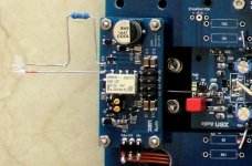
While preparing for the test platform for the Pioneer Super Linear HPA,
The Pioneer Super Linear Circuit
I built another SHPP for +/-15V, and added the off-board LED and R20.
Note that the value of R20 should be reduced by ~700R when using a blue LED (to allow for the voltage drop of the latter).
A mute switch can simply be added in series with the LED.
It will allow you to manually break the supply circuit for the protection relay.
QED.")
Patrick
.
The Pioneer Super Linear Circuit
I built another SHPP for +/-15V, and added the off-board LED and R20.
Note that the value of R20 should be reduced by ~700R when using a blue LED (to allow for the voltage drop of the latter).
A mute switch can simply be added in series with the LED.
It will allow you to manually break the supply circuit for the protection relay.
QED.
Patrick
.
Attachments
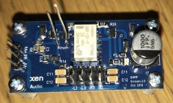
I got my SHPP board to a phase where I could test it and to my surprise it seems to be working alright. This was the most difficult soldering job I have encountered so far and my handcraft aint pretty. I have propably made a mistake with the LEDs, since the only one I can see lit is the right channel red one, when I feed DC to that channel with battery as described in the documents. When I feed DC to left channel the relay clicks, so I suppose it’s functioning as it should although the red LED won’t lit up. The green and yellow LEDs won’t lit no matter what I do. I guess that the LEDs are only for indication and don’t affect the protection functionality? I really hope I don’t have de-solder all the LEDs.
My other question is do I connect only Li and Ri (in SHPP board) from the headphone amp and Lo and Ro from SHPP to headphone out? Ground only to SHPP board’s power ground? Just to be sure...
My other question is do I connect only Li and Ri (in SHPP board) from the headphone amp and Lo and Ro from SHPP to headphone out? Ground only to SHPP board’s power ground? Just to be sure...
Attachments
Firstly none of the LEDs should light up even under DC offset.
So your circuit should be working as intended.
If you read the documents again, the SHPP can be used for any headamp output, including single ended and balanced ones.
So you need to connect all 4 connections (Li+, Li-, Ri+, Ri-) to you headamp outputs.
In addition you need to connect the SHPP PSU Gnd to the Gnd of one of the headamps.
If you use the headamp supply also for the SHPP, this is done automatically.
I personally use separate power supplies (78Lxx/79Lxx) for the SHPP.
You should also connect all 4 connections (Lo+, Lo-, Ro+, Ro-) from SHPP to the headphone.
I always use 4-pin connectors for headphones, as I want the Gnd current to return to their respective amplifier through separate wires to minimise cross talk.
I use either 5-pin Mini XLR (Pin 5 left unused) or 3.5mm TRRS.
Soldering will improve a lot after 2 or 3 boards.
The trick is to start from the middle and work outwards for good access.
And very sharp soldering iron tips.
Patrick
Ok, I got it for the headphone connections. Thanks for clarification.
"Firstly none of the LEDs should light up even under DC offset."
So what is the purpose of the LEDs? The red one on my right channel does lit up and relay turns off when I feed dc to Ri+/Ri-, and dims out within few seconds after I remove the dc. Also shorting the reset pins turns D1 off. On the left channel the D1 does not lit while doing similiar tests but the relay works as it should. Is this still proper functioning?
Under normal circumstances, the voltage across D1 should not be much more than Vbe of Q3, i.e. 0.6V.
They are there to prevent excessive voltages in case of a fault.
In my own examples, the red leds only light up when there is a huge DC transient.
If you slowly turn up the DC, as normally the case, they should not light up.
Re-read the pdf and try to understand how the circuit functions.
I would check that first, then check soldering of R5,6,7, D1,2, and Q1,2.
What is your supply voltage and what value of R5,6,7 are you using ?
And what DC offset did you use to test (100mV or so ?)
Patrick
Last edited:
The board is set up to be used with +-24V supply. R5/R6 = 27k and R7 = 10k according to the BOM I got from the group buy. I need to check on the DC offset, maybe I had too high a value and that’s why the led lit up.
Yes, I need to take more time trying to understand this circuit and check the solder joints. I'm just being overly cautious since I'm not confident about my smd soldering on this board. Thanks a lot for helping.
Yes, I need to take more time trying to understand this circuit and check the solder joints. I'm just being overly cautious since I'm not confident about my smd soldering on this board. Thanks a lot for helping.
Last edited:
The values are correct.
This is an example explanation :
The first opamp stage has a gain of 6 at DC.
Suppose you put -1V DC at the +ve input, the opamp output will be -6V.
The voltage across D1 is ~ 1.8V when it lights up.
This will be the case when it equals Vbe Q3 + V across R8 + V across D2.
i.e. current through R8 ~0.06mA.
And the current through R7 would then be ~2.8mA which is more or less equal to current through D1.
In the worst worst case, the opamp output is at -24V under -4V DC, and the current through D1 and R7 is about 5mA.
R7 will get very hot, and probably needs replacement afterwards if exposed to that condition for a long time.
But this is the most unusual case and your amp needs a lot more attention anyhow in that case.
You should use a 9V battery and a trimpot to apply the DC offset gradually, both positive and negative.
Then see when the relay triggers.
This will tell you the positive and negative trigger point of each channel.
The other channel not under test should have both inputs connected to Gnd.
Connecting the LED in series as in post #29 makes it easier to tell when it triggers.
Patrick
I attached a Spice file for you to play with.
Should help you understand the circuit more.
Some components have been changed to use those in the Spice library.
These changes has no effect on the functioning of the circuit.
Feel free to change things around to see how they affect :
opamp output
relay current
current through D1, D2
etc.
Have fun,
Patrick
.
Attachments
 Thanks!
- Home
- Amplifiers
- Headphone Systems
- XEN SHPP -- Simple Headphone Protection