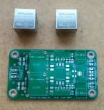
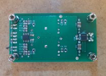
Today I finally got the time to do some soldering. SMD parts are almost done. The only parts missing are the rails indicator LEDs and CM choke. They are on their way to me from mouser at the moment.
Attachments
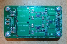
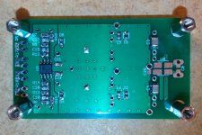
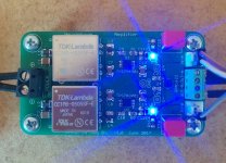
Finally finished the headamp!
All works as intended! Oscilloscope does not show any ripple/noise if measured across V-, GND and V+ terminals at the PSU section output. PSU output voltages measure -5.003V and +5.013V (regulators headroom is 1V). I measure slight 100MHz noise at the output terminal of the headamp but I guess this is mostly pickup noise by the probe. The THD measures the same as the other implementations posted earlier in this thread. I haven't listened to the headamp yet but I do not expect any surprises here.
One more thing which was not mentioned before: the headamp is short circuit safe at all stages! DC-DC converters can be shorted for as long as 30s without damage, the regs have built-in short circuit protection, OPA2140 and OPA1622 are short circuit safe too! So no problem with slipped probes shorting something (happened recently).
I am very happy with the outcome")
Regards,
Oleg
All works as intended! Oscilloscope does not show any ripple/noise if measured across V-, GND and V+ terminals at the PSU section output. PSU output voltages measure -5.003V and +5.013V (regulators headroom is 1V). I measure slight 100MHz noise at the output terminal of the headamp but I guess this is mostly pickup noise by the probe. The THD measures the same as the other implementations posted earlier in this thread. I haven't listened to the headamp yet but I do not expect any surprises here.
One more thing which was not mentioned before: the headamp is short circuit safe at all stages! DC-DC converters can be shorted for as long as 30s without damage, the regs have built-in short circuit protection, OPA2140 and OPA1622 are short circuit safe too! So no problem with slipped probes shorting something (happened recently).
I am very happy with the outcome
Regards,
Oleg
Attachments
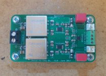
Today I finally got the time to measure and listen to the headamp. The measurements did not reveal anything anomalous. They look the same as my other measurements earlier in this thread. The distortion seems immaterial at least when using Focusrite 2i2 for measurements even if driving 32 Ohm dummy load.
Brief listening did not reveal any artifacts. The headamp is dead silent between tracks. It also has no turn on/off thump with and without signal thanks to the EN pin of the OPA1622 controlled by resistor-LED voltage divider: the amp turns on when positive rail is at around +4V. Since positive and negative regs have similar start up delay due to identical RC networks at their NR/SS pins, both rails come up simultaneously and thus the OPA1622 and OPA2140 are already fully operational when rails reach +(-)4V. The amp turns off nearly instantly since there is very little storage capacitance on board.
So I am very satisfied with the headamp!
Regards,
Oleg
Last edited:
Originally I planned to use OPA1642 which according to johnc124 is one of the beast measuring JFET input op-amps from TI. The advantage of such op-amp is immunity to the source impedance. OPA2140 has been suggested to me by agdr when I expressed my concern regarding 3.5 mV max input offset voltage of OPA1642, which can be a problem especially if you give it some gain. In contrast OPA2140 has 250uV max offset but all other parameters are the same as for the OPA1642, so OPA2140 looks like a precision version of OPA1642. Thus with OPA2140 I have the same low distortion as with OPA1642 but negligible input offset and thus no DC at the output of the headamp.
Outstanding work, OlegSh! Very well done. Your amp represents a lot of design effort. Is the schematic in post #237 the latest?
I'm a guy who has always avoided switching power supplies in low-power audio designs (headphone amps, pre-amps) at all costs to keep switching noise out, but I have to admit switchers are a necessity now. AC-AC transformers have become nearly non-existent over the last year or two, making the half-wave voltage-doubler type of linear supply in the O2 headphone amp impossible going forward. Putting a 50/60Hz power transformer on a headphone amp PC board is really a non-starter now given the size and magnetic field leakage issues at 50/60Hz. What you have done seems to be the way to deal with switchers in audio now. Follow them with RF LDOs to clean up the output. Then shield the heck out of the thing, if necessary.
I know Sergey888 has had success too (measured, on his SR1) with the switcher in his Crocodile headphone amp design. You guys are proving that using switchers in audio can be successfully done in DIY!
Last edited:
Originally I planned to use OPA1642 which according to johnc124 is one of the beast measuring JFET input op-amps from TI. The advantage of such op-amp is immunity to the source impedance. OPA2140 has been suggested to me by agdr when I expressed my concern regarding 3.5 mV max input offset voltage of OPA1642, which can be a problem especially if you give it some gain. In contrast OPA2140 has 250uV max offset but all other parameters are the same as for the OPA1642, so OPA2140 looks like a precision version of OPA1642. Thus with OPA2140 I have the same low distortion as with OPA1642 but negligible input offset and thus no DC at the output of the headamp.
Thank you for your reply.
I'll add a couple to my next Mouser order to try.
An externally hosted image should be here but it was not working when we last tested it.
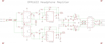
Here is my first cut at a USB DAC and Headphone amplifier I've been working on it utilizes the XHRA-2HPA XMOS USB to I2S converter, a PCM1794A DAC and a OPA1622 output amplifier. I designed this to be able to drive 50ohm (HD598) to 300ohm headphones (HD650).
I'm not 100% sure about using the OPA1622 as a unity gain buffer, I would have liked to use the OPA1622 as a difference amplifier as suggested in the datasheet but I wanted volume control and was unsure of a 4-gang pots performance. Any comments or suggestions are welcome.
I'm not 100% sure about using the OPA1622 as a unity gain buffer, I would have liked to use the OPA1622 as a difference amplifier as suggested in the datasheet but I wanted volume control and was unsure of a 4-gang pots performance. Any comments or suggestions are welcome.
Attachments
Hi,
Before submitting the next PCB revision for manufacturing I wuld like to measure the performance of the headamp shown in post #246 using something significantly better than Focusrite Scarlett 2i2 interface. Could someone from Germany or at least from the continental part of EU be willing to help with that? I'll pay the round postage. Please PM if interested.
Regards,
Oleg
- Status
- This old topic is closed. If you want to reopen this topic, contact a moderator using the "Report Post" button.
- Home
- Amplifiers
- Headphone Systems
- Universal buffer/headamp based on OPA1622