The thermal pad has to be connected to the most negative supply externally. It should also be soldered to the copper pour for heat sinking. The other pins do not protrude outside of the package but as is typical in electronics all the pins should be soldered to the respective pads on the PCB")
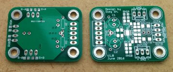
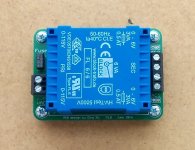
PCBs arrived!
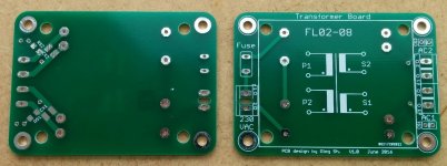
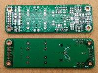
All is fine except there are some traces left from the snubber circuit on the bottom layer of the PCB with PSU (next to the PSU input connector) and there are two exposed GND pads next to the power pads of the regs. Electrically everything is fully OK. Just aesthetics The CRC transformer snubber is now on the transformer board.
The other PCBs are all OK.
Regards,
Oleg
All is fine except there are some traces left from the snubber circuit on the bottom layer of the PCB with PSU (next to the PSU input connector) and there are two exposed GND pads next to the power pads of the regs. Electrically everything is fully OK. Just aesthetics
The CRC transformer snubber is now on the transformer board.The other PCBs are all OK.
Regards,
Oleg
Attachments
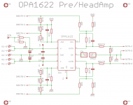
I have also made reduced version of the pre/head amp without the PSU part. This PCB is only 3x4 cm in size. I am going to order both designs with and without the PSU. Most probably I'll get a dozen of each design but I need only fraction of it. So I'm curious if there is interest in such PCBs from forum members?
Regards,
Oleg
Hey Oleg, I'd definitely be interested in a couple of the reduced boards and 1 of the larger boards.
Another PCB design
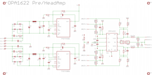
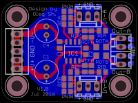
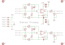
Have been playing with Eagle CAD... Always wanted to design a small PCB for buffer/preamp based on dual op-amp in SOIC8 package. The preliminary PCB version is attached. Similar to OPA1622 PCBs this one also allows inverting/non-inverting/differential configurations. The PCB is not suitable for automated assembly due to tight spaces between parts but manual assembly using conventional soldering iron should be relatively easy.
Please have a look and let me know if I overlooked something.
Regards,
Oleg
Attachments
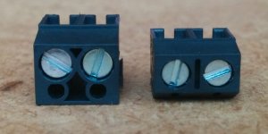
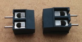
I am currently looking for a suitable headphone jack socket which would fit on the 8~10 mm thick front panel. I'm planing to use 6.3 mm guitar sockets like these since they have very long thread. Does anybody have an experience with them, how reliable/robust these sockets are? I'd like to be confident that they are OK before drilling large hole in the front panel.
Thanks,
Oleg
Thanks,
Oleg
- Status
- This old topic is closed. If you want to reopen this topic, contact a moderator using the "Report Post" button.
- Home
- Amplifiers
- Headphone Systems
- Universal buffer/headamp based on OPA1622