44kHz measurements
...turned on without problem the module. Attached at once the usb converter,
and I'm feeding it with the power bank.
PS supplies are +- 5V down to mV precision.
Output offset is .1mV both channels. (it's more the error of the multimeter)
Gain=2
Vpp out = 8V before clipping, with no load (10kohm of soundcard)
A bit below with 390 ohm load.
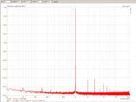
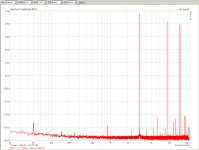
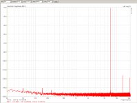
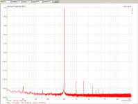
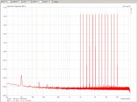
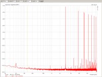
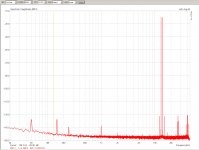
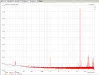
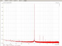
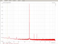
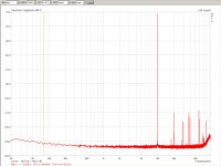
So, here there are the distortion tests made with the EMU1616m (mod)
soundcard, at a level of ~<10db, (!1Vrms input, 2Vrms out) at the point
where output clipping distrotion has just disappeared
I did at 44khz for lowering the residual distortion of the soundcard.
Your unit measures very much into the distortion floor of my soundcard.
The values a tiny bit higher that the best residual level of the card.
It's only visible at higher freqencies, like at 10kHz and IMD where it is
perceivably higher, but still very small and very clean for your module.
...turned on without problem the module. Attached at once the usb converter,
and I'm feeding it with the power bank.
PS supplies are +- 5V down to mV precision.
Output offset is .1mV both channels. (it's more the error of the multimeter)
Gain=2
Vpp out = 8V before clipping, with no load (10kohm of soundcard)
A bit below with 390 ohm load.
So, here there are the distortion tests made with the EMU1616m (mod)
soundcard, at a level of ~<10db, (!1Vrms input, 2Vrms out) at the point
where output clipping distrotion has just disappeared
I did at 44khz for lowering the residual distortion of the soundcard.
Your unit measures very much into the distortion floor of my soundcard.
The values a tiny bit higher that the best residual level of the card.
It's only visible at higher freqencies, like at 10kHz and IMD where it is
perceivably higher, but still very small and very clean for your module.
Attachments
-
 OL_HD_1khz_-11db_2.5Vrms_10kohmload_44kHzsampl_real1k.jpg426.6 KB · Views: 371
 -
 OL_HD_SMPTE_IMD_-12db_2Vrms_10kohmload_44kHzsampl_crippled.jpg410.9 KB · Views: 102
 -
 OL_HD_MULT_ITU_-8db_2Vrms_10kohmload_44kHzsampl.jpg510.8 KB · Views: 101
 -
 OL_HD_MULT_High_-10db_2Vrms_10kohmload_44kHzsampl.jpg475.4 KB · Views: 324
 -
 OL_HD_MULT_DIM_-10db_2Vrms_10kohmload_44kHzsampl.jpg441.6 KB · Views: 359
 -
 OL_HD_7khz_-11db_2Vrms_10kohmload_44kHzsampl.jpg431.7 KB · Views: 364
 -
 OL_HD_1khz_-11db_2Vrms_10kohmload_44kHzsampl_r.jpg434.7 KB · Views: 368
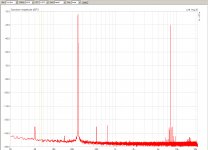
88kHz measurements
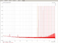
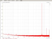
Here are the 88kHz tests. You can see better the high freq. behavior and,
because the module's distortion is a tiny bit higher than the sound card
baseline, so I could repeat the tests at 88khz with basically the same
results, same distortion values.
Here are the 88kHz tests. You can see better the high freq. behavior and,
because the module's distortion is a tiny bit higher than the sound card
baseline, so I could repeat the tests at 88khz with basically the same
results, same distortion values.
Attachments
-
 OL_HD_MULT_High_-10db_2Vrms_10kohmload_88kHzsampl.jpg478.3 KB · Views: 71
 -
 OL_HD_MULT_DIM_-11db_2Vrms_390ohmload_88kHzsampl.jpg480 KB · Views: 78
 -
 OL_HD_DIM_-12db_2Vrms_10kohmload_88kHzsampl.jpg480.3 KB · Views: 74
 -
 OL_HD_10khz_-11db_2Vrms_390ohmload_88kHzsampl.jpg436.4 KB · Views: 69
 -
 OL_HD_10khz_-11db_2Vrms_10kohmload_88kHzsampl_crippled.jpg402.1 KB · Views: 68
 -
 OL_HD_1khz_-11db_2Vrms_390ohm-load_88kHzsampl.jpg442.2 KB · Views: 78
 -
 OL_HD_1khz_-11db_2Vrms_10kohmload_88kHzsampl.jpg440.9 KB · Views: 83
36 Ohm load
So here they are the measurements with 36 ohm (sorry, I had this one at hand, no 32 ohm all over the place..)
Here one start to see the effects. Still very very good.
First, the usual 44khz group
So here they are the measurements with 36 ohm (sorry, I had this one at hand, no 32 ohm all over the place..)
Here one start to see the effects. Still very very good.
First, the usual 44khz group
Attachments
36 Ohm load (88kHz)
This is the group of 88khz sampling, single tone measurements
This is the group of 88khz sampling, single tone measurements
Attachments
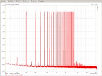
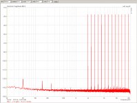
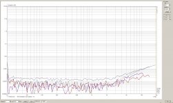
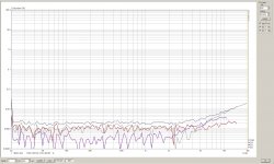
88kHz multitone tests
This is the group of multitone tests.
The 'highcap-bank' note wanted to denote the use of a 10000mAh power bank,
instead of the small one generally used. Wanted to see if there is a
difference, depending on the source internal impedance (before the dc-dc
converters)
This is the group of multitone tests.
The 'highcap-bank' note wanted to denote the use of a 10000mAh power bank,
instead of the small one generally used. Wanted to see if there is a
difference, depending on the source internal impedance (before the dc-dc
converters)
Attachments
-
 OL_HD_MULT_ITU_-7db_2.1Vrms_36ohmload_88kHzsampl.jpg509.6 KB · Views: 74
 -
 OL_HD_MULT_High_-11db_2.1Vrms_36ohmload_88kHzsampl.jpg485.4 KB · Views: 69
 -
 OL_HD_MULT_High_-10db_2.1Vrms_36ohmload_88kHzsampl_highcap_bank.jpg478.1 KB · Views: 68
 -
 OL_HD_MULT_High_-10db_2.1Vrms_36ohmload_88kHzsampl.jpg484.4 KB · Views: 66
 -
 OL_HD_MULT_DIM_-12db_2.1Vrms_36ohmload_88kHzsampl.jpg484 KB · Views: 78
 -
 OL_HD_IMD_-12db_2.1Vrms_36ohmload_88kHzsampl.jpg464.7 KB · Views: 68
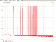
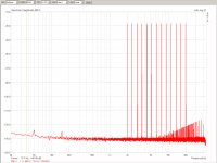
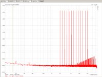
Distortion vs. Frequency
Finally, the distortion vs. frequency scans, they are two because the
first is an intermediate value, not at the usual 2.1V rms output level. I
still have to see, but it was at like half magnitude of that, 1.1V rms.
The file signed with +4db is the real max output level, 2.1Vrms.
Then I had included the distortion plots made at max sample rate, just to
see if there is any 'intrusors' at the higher frequency range, like
because of the switching PS noise mixing down.
No such sign of any deviations, all normal usual soundcard scene.
Attachments
Oscilloscope shots
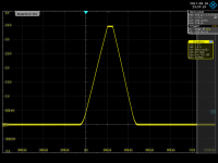
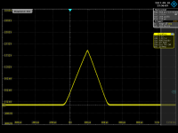
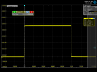
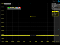
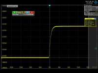
Here you are, the transient behavior of the unit, tested with square wave
signal and triangular -- for clean show of clipping.
The test load was the scope's 50 Ohm termination itself, So did not have to
bother with termination problems and reflections (ok, not a prob. at these
frequencies)
Here you are, the transient behavior of the unit, tested with square wave
signal and triangular -- for clean show of clipping.
The test load was the scope's 50 Ohm termination itself, So did not have to
bother with termination problems and reflections (ok, not a prob. at these
frequencies)
Attachments
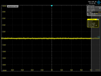
Switching noise
Then, I had a second look at the switching noise again.
This time I found out that it does not disappear -- after some poking I
had realized that in practice it had never gone away: only with my old
analog scope beauty it has decreased level and glitch narrowness that the
scope got into triggering difficulties and so did not show on screen a
stable pic of the noise signal. So it seemed decreased.
So, this scope is a beast and cannot be let down so easily.
So the basic - constant response what I got is something like this:
(First pic in attach)
the second attach is the zoomed version showing the very narrow spike
All this really goes away if I set the scope input filter to 20MHz
(third attach)
Attachments
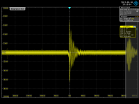
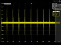
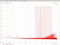
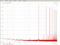
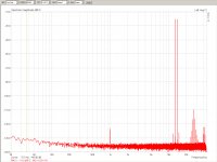
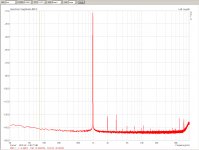
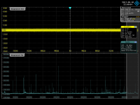
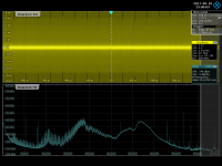
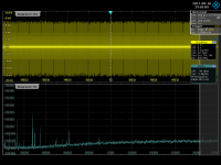
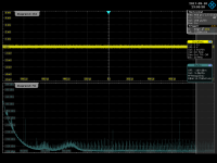
Oscilloscope shots and FFT analysis
Ok, previously I have shown the noise signal in time. How does it look
like in the frequency domain?
First attach here is the scope and setup noise baseline, that is,
everything connected but the headamp not powered up.
Second attach is the head amp powered up
Third one is the same but low frequency zoom in
Fourth is with 20MHz filter activated
Conclusion: as you can see the narrow pulse series yields a spectral
distribution which is peaking at about 400MHz.
At around and below 20MHz there is very small amount of noise signal
energy accumulated, so a 20MHZ highpass filter removes most of the noise.
But: all this perturbation is a result of picking up the radiated EMI
fields. So it will go into everything, like into the level control
potentiometer, or the input cabling itself.
So it's not a very good thing, because then it gets into the amplification
chain itself, and could cause problems.
Mind You, in the previous distortion measurements it did not cause major
deviations..
What I noted is that 'fingering' the metal shields of the DCDC converters
is decreasing the picked up signal. And it's not a grounding effect. Not
only. an isolated water bag does similar effect.
It is the RF absorbing / damping effect that is at work.
So my conclusion is that maybe, very probably some RF absorber ferrite
doped sheet, ERS Clothe, things like that could be a positive cure...
Attachments
- Status
- This old topic is closed. If you want to reopen this topic, contact a moderator using the "Report Post" button.
- Home
- Amplifiers
- Headphone Systems
- Universal buffer/headamp based on OPA1622