Hello all,
I came across a nice, simple circuit for a low distortion buffer that I'm thinking of using as a unity-gain headphone amp. I already have most of the parts in my bin, and it's straightforward enough for me to tackle.
My DAC output is pretty juicy, so I really don't need gain. I've attached the schematic below. What do you guys think of it?
The only thing I'm unsure of is what D1 and D2 represent. Are they constant current diodes? If so, what is the "2.0" likely to mean? Surely not amps") . Is the 47uF input coupling cap a bit much? From what I've read it doesn't need to be anywhere near that big.
. Is the 47uF input coupling cap a bit much? From what I've read it doesn't need to be anywhere near that big.
I came across a nice, simple circuit for a low distortion buffer that I'm thinking of using as a unity-gain headphone amp. I already have most of the parts in my bin, and it's straightforward enough for me to tackle.
My DAC output is pretty juicy, so I really don't need gain. I've attached the schematic below. What do you guys think of it?
The only thing I'm unsure of is what D1 and D2 represent. Are they constant current diodes? If so, what is the "2.0" likely to mean? Surely not amps
. Is the 47uF input coupling cap a bit much? From what I've read it doesn't need to be anywhere near that big.Attachments
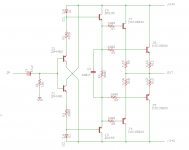
They will be constant current diodes, probably 2ma. LED's would just turn on J3 and J6 destructively. They could be replaced by resistors but you would have to calculate and simulate it. It would work though.
These are basic circuits and you will find big differences in simulated values and real world components. The DC offset could be disappointing without individual tweaking or adding a servo.
These are basic circuits and you will find big differences in simulated values and real world components. The DC offset could be disappointing without individual tweaking or adding a servo.
Hmmm..., parallel output transistors and 24V supply voltages, I would estimate output power about 30W in 8 ohms. IMHO plenty oversized for a headphone buffer.
47µ for electrolytic coupling cap isn´t that unusual, but you will find a lot of different and controversial opinions and discussions about this topic.
O.K., but why zener diodes in forward direction are used?They will be constant current diodes, probably 2ma. LED's would just turn on J3 and J6 destructively. They could be replaced by resistors but you would have to calculate and simulate it. It would work though.
47µ for electrolytic coupling cap isn´t that unusual, but you will find a lot of different and controversial opinions and discussions about this topic.
30W you say? Hmmm... since I lack constant-current diodes, and don't yet have plans to strap a pair of full-size speakers to my head I'll give jam's circuit a try . What supply voltage would be best?
Are there any other headphone buffer recommendations? I'll also do some searching.
. What supply voltage would be best?Are there any other headphone buffer recommendations? I'll also do some searching.
Last edited:
i'm a chicken,
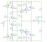
i'd be too worried about #1 being a headphone oscillator.
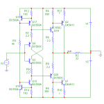
#2 is interesting; i'll pass on the filter (pardon the pun), personally, i'd like a little more beef for the outputs.
i feel like i've seen something very similar before ... time to visit the archives ...
mlloyd1
i'd be too worried about #1 being a headphone oscillator.
#2 is interesting; i'll pass on the filter (pardon the pun
), personally, i'd like a little more beef for the outputs. i feel like i've seen something very similar before ... time to visit the archives ...
mlloyd1
- Status
- This old topic is closed. If you want to reopen this topic, contact a moderator using the "Report Post" button.
- Home
- Amplifiers
- Headphone Systems
- No-gain diamond buffer headphone amplifier advice