It appears very similar although with different values and references.
And im back with more problems, or tbh the same problem.
Now when im following the guide for the stripboard version, i got a bit worried. in this guide the resistors 5 and 6 is at 1k, and r7/8 is at 10k. I'm not that good with schematics but is it not r7/8 that controls the gain?
if it is r7/8 can i still use the 10k resistors there or will it mess up the whole build!?
Its the ratio of the resistors that set the gain.
In the stripboard layout R7/8 are 10k and R5/6 are 1k. R3/4 are 100k and R1/2 the 4.7k
Yeah, you kind lost me there, ill read in to it. But can i use 10k resistors instead of 1k resistors?
The PDF in post #3 shows R4 as being 10k.
In the stripboard layout that has changed to R7/R8. These should be 10k. They are the resistor that connects between pins 1 and 2 and pins 6 and 7 of the opamp.
Ey Mooly!
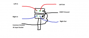
Back again with more questions! I'm just now getting time to mount the off board components, like audio in and audio out etc. Well, i'm not really sure where how to wire left/right channels to the pot then to the out, and same with the audio in, How do i know what is left and what is right channel? There was no info in the product page i got as pdf :V
Help please! Really want the amp ready for monday
The pot is easy. Place it in front of you and with the pins facing upward. Attach the wires as shown. There is no 'left' and 'right' as such. Its up to you to decide which is which when you connect it all. If you found the channel reversed when listening then all you do is swap either the input or the output wires over.

The output socket also has a common ground that goes back to the CMOY ground.

The output socket also has a common ground that goes back to the CMOY ground.
The pot is easy. Place it in front of you and with the pins facing upward. Attach the wires as shown. There is no 'left' and 'right' as such. Its up to you to decide which is which when you connect it all. If you found the channel reversed when listening then all you do is swap either the input or the output wires over.
View attachment 538647
The output socket also has a common ground that goes back to the CMOY ground.
Well, I got all the cables on the pot and in/out. But I'm a little bit lost where I connect all the ground wires. Also I did not understand what you were saying about the output ground ☺️
An externally hosted image should be here but it was not working when we last tested it.
Either I'm blind or he didn't show on this render where I put the ground wires
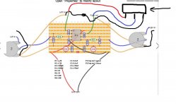
Those orange coloured wires are the grounds.
Its much much harder to describe than to just do it. The rectangle at the right is the headphone socket with the plug coming in at the right. All you really need is a single wire for the ground returning the headphone socket ground to the virtual ground on the board which is the junction of C3 and C4.
The input ground is wired the same way to whatever sockets you have chosen.

Those orange coloured wires are the grounds.
Its much much harder to describe than to just do it. The rectangle at the right is the headphone socket with the plug coming in at the right. All you really need is a single wire for the ground returning the headphone socket ground to the virtual ground on the board which is the junction of C3 and C4.
The input ground is wired the same way to whatever sockets you have chosen.
View attachment 538663
Ahh i get it! Thanks again!
also i just realised i put the ic socket the wrong way? but that wont ruin anything right? If i just put the ic the right way it will work perfectly fine right?
Sounds like you might have a missing ground on either the input side of things or the output side to the 'phones.
You can post pictures if you wish, but its never easy to follow things that way. Do the checks and measurements.
Here are pictures Imgur: The most awesome images on the Internet
Also, you said do the checks and measurements. Is there some list of things i check with the dmm. Cus me just checking would not get me nowhere cus i dont know what values i should expect
Thanks again for being to helpful with this!
Basic checks.
1/ Switch off and remove the batteries.
2/ Have your meter set to a low ohms range.
3/ Now check that the red wire in the first picture (the one with the headphone socket) goes to the 'virtual ground point' which is the junction of C1+ and C1- in the diagram you linked to in post #3.
4/ Check that the wire's going to the volume control (the pins that are joined and with those two blue and two red wires attached) also go to the virtual ground.
5/ Check that the input grounds also go to this same point.
6/ Now power it all up.
7/ Set your meter to DC voltage and connect the black lead to the virtual ground point.
8/ Check that you have +9 or so volts on pin 8 of the opamp.
9/ Check that you have -9 volts on pin 4.
10/ Check that the voltage on pins 1,2 and 3 is zero and that the voltage on pins 5,6 and 7 is zero.
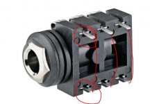
I'm assuming that the other smaller socket is for the input ? Measure the continuity from the part of the socket that is at the front (where the big nut is) to the 3 pins on the back of the socket. It will connect to just one of the pins and have continuity. That pin is ground, and is the one that must go to the virtual ground point.
Basic checks.
3/ Now check that the red wire in the first picture (the one with the headphone socket) goes to the 'virtual ground point' which is the junction of C1+ and C1- in the diagram you linked to in post #3.
Well, i connected this wire to my stack of pot ground wires, so it would be easier to cable manage it later. but it is connected to the virtual ground. Same with the input. If you check the second picture the red wires conected to the "ground pins" are input and output wires, and the 2 blue wires are the ones that are connected to the virtual ground.
But ill do all the checks you gave me and come back.
Basic checks.
1/ Switch off and remove the batteries.
2/ Have your meter set to a low ohms range.
3/ Now check that the red wire in the first picture (the one with the headphone socket) goes to the 'virtual ground point' which is the junction of C1+ and C1- in the diagram you linked to in post #3.
4/ Check that the wire's going to the volume control (the pins that are joined and with those two blue and two red wires attached) also go to the virtual ground.
5/ Check that the input grounds also go to this same point.
6/ Now power it all up.
7/ Set your meter to DC voltage and connect the black lead to the virtual ground point.
8/ Check that you have +9 or so volts on pin 8 of the opamp.
9/ Check that you have -9 volts on pin 4.
10/ Check that the voltage on pins 1,2 and 3 is zero and that the voltage on pins 5,6 and 7 is zero.
I'm assuming that the other smaller socket is for the input ? Measure the continuity from the part of the socket that is at the front (where the big nut is) to the 3 pins on the back of the socket. It will connect to just one of the pins and have continuity. That pin is ground, and is the one that must go to the virtual ground point.
Well, i connected this wire to my stack of pot ground wires, so it would be easier to cable manage it later. but it is connected to the virtual ground. Same with the input. If you check the second picture the red wires conected to the "ground pins" are input and output wires, and the 2 blue wires are the ones that are connected to the virtual ground.
But ill do all the checks you gave me and come back.
Done it. and everything looked good, 8 and 4 is shoring 9v and the rest is at 0.02ish. But there is 1 thing im not sure about. My 6.3mm output, if i use my dmm and try to measure between the points marked(https://gyazo.com/4a1cdac7c91e423cd065b3b7bf42f0e6). i get no reading at all, which means that i don't have a connection right? Can this be the problem?
Last edited:
In the 5th photo down at the bottom left of the board, there looks to be an unsoldered wire. Also between tracks 5 and 6 from the top, to the right of the chip, there may be a whisker of solder.
Give the board a good clean with a tooth brush and isopropyl alcohol (or vodka) to get rid of the soldering residue and drag a blade between the tracks to make sure there are no whiskers.
John
Give the board a good clean with a tooth brush and isopropyl alcohol (or vodka) to get rid of the soldering residue and drag a blade between the tracks to make sure there are no whiskers.
John
HEYO!
Now its working, turns out the op275 chips i got are both bad? cus when i switched to one of my tle2082cp it sounds "great"(cus i use shitty sub 1$ headphones to test).
But if they are working with a pair of shity old headphones, how do i check so the amp is "safe" for use? Is there any last checks i should do?
- Status
- This old topic is closed. If you want to reopen this topic, contact a moderator using the "Report Post" button.
- Home
- Amplifiers
- Headphone Systems
- Need help pre CMOY build
