Would appreciate help to diagnose / repair a "bonehead" move I when modding an Indeed G2 single 12AU7 head amp. These have been around for years and sold under brands Indeed, Little Bear, and Bravo.
I was attempting to change the Vout resistance from the LM317 from 4.3R to 5.6R.
The original circuit uses two resistors in parallel to achieve 4.3R.
Instead of just removing one of the two parallel resistors and replacing with one 5.6R, I replaced one of the resistors with a wire link which resulted in a dead short. (bonehead move!)
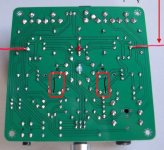
See the attached of the circuit board bottom showing what I did,and circuit schematic.
The resistor positions are highlighted in the red boxes, and the black lines shows where I put the wire links.
Despite replacing the LM317s and IRF630s and putting the original resistors back, the sound output is almost nothing and very distorted.
Anode voltage adjustment still works fine and do not see any fried circuits up or downstream. Also know the tube is working fine.
Need help figuring out what else is wrong.
Thank you in advance for any assistance!
I was attempting to change the Vout resistance from the LM317 from 4.3R to 5.6R.
The original circuit uses two resistors in parallel to achieve 4.3R.
Instead of just removing one of the two parallel resistors and replacing with one 5.6R, I replaced one of the resistors with a wire link which resulted in a dead short. (bonehead move!)
See the attached of the circuit board bottom showing what I did,and circuit schematic.
The resistor positions are highlighted in the red boxes, and the black lines shows where I put the wire links.
Despite replacing the LM317s and IRF630s and putting the original resistors back, the sound output is almost nothing and very distorted.
Anode voltage adjustment still works fine and do not see any fried circuits up or downstream. Also know the tube is working fine.
Need help figuring out what else is wrong.
Thank you in advance for any assistance!
Attachments
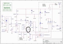
Measure the voltage across the 4.3 ohm. It should around 1.5 volts. Also confirm that the 9 volts shown is somewhere around that value.
Are you sure the valve is OK ? Shorting the 4.3 ohm out would (as far as I can tell) effectively put a higher than expected voltage across the filaments.
Are the two 68 ohms OK ?
Are you sure the valve is OK ? Shorting the 4.3 ohm out would (as far as I can tell) effectively put a higher than expected voltage across the filaments.
Are the two 68 ohms OK ?
Measure the voltage across the 4.3 ohm. It should around 1.5 volts. Also confirm that the 9 volts shown is somewhere around that value.
Are you sure the valve is OK ? Shorting the 4.3 ohm out would (as far as I can tell) effectively put a higher than expected voltage across the filaments.
Are the two 68 ohms OK ?
Hi Mooly,
Thank you for your suggestions; all of the above checked out okay which stumped me.
Problem solved. Turns out there was a problem with the delay circuit resistors and/or cap.
Changed them all and the amp works fine now.
Are you familiar with the mods to this amp?
Did the B+ power mod to pin 4 using the Traco TRS 1-2465 circuit; and it worked fine for about an hour, then started frying the 100uH inductor.
Sounded very good while it lasted though.
Put back to stock and the amp still works fine again.
Pleased to hear you have fixed it 
I'm afraid I'm not familiar at all with the amp, lol, in fact I don't normally venture into glass bottle territory... but as this one had a bit of silicon lurking in there")
(Would have to see the circuit showing the 100uH and where it fits into the scheme of things to have any idea what might have happened)
I'm afraid I'm not familiar at all with the amp, lol, in fact I don't normally venture into glass bottle territory... but as this one had a bit of silicon lurking in there
(Would have to see the circuit showing the 100uH and where it fits into the scheme of things to have any idea what might have happened)
- Status
- This old topic is closed. If you want to reopen this topic, contact a moderator using the "Report Post" button.