Dear DIYers,
I decided to throw myself on a DIY Lehmann BCL clone. I am a beginner and you should treat me as a fresh one.
I know my soldering and how to work clean and I'm a perfectionist but next to that I have barely the proper knowledge to make right decisions on circuitry.
Lately I have been reading a lot on this forum and other forums to gather more knowledge about different parts and what they are supposed to do. Got me a little wiser but not anything near my goal. That's why I want to share my project here. I hope to get some good tips here about my next few steps.
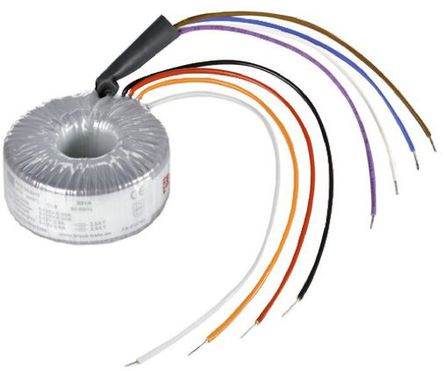
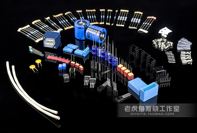
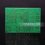
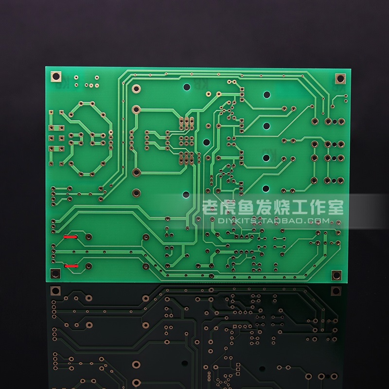
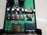
Since I am currently located in China, I can get my hands on a lot of parts easily and cheap and I ordered a clone PCB and a package of parts that was supposed to be almost identical to the latest version of the original BCL. The components are genuine from RS-components. The tranformer used was a german made BLOCK 40VA instead of the original custom made 30VA.
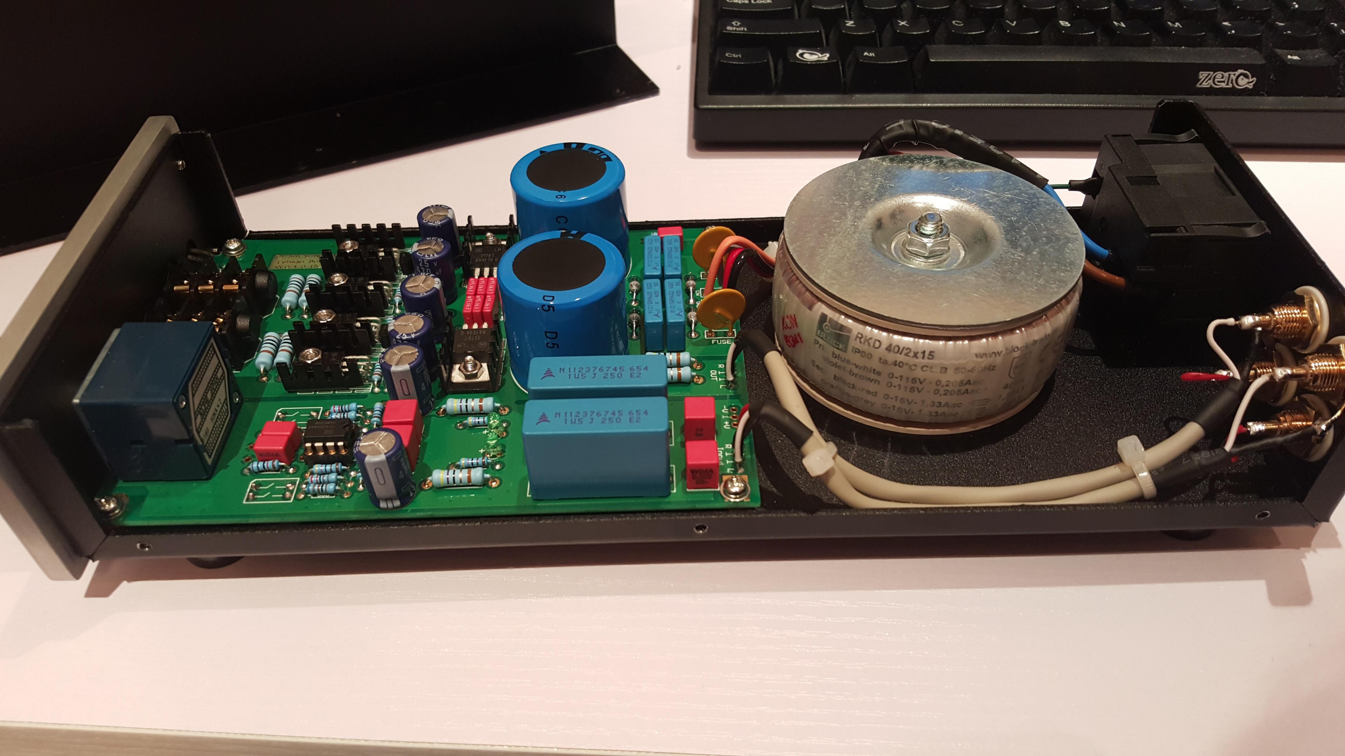
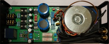
After I put it all together and put it up for the smoke test all worked fine and I was amazed what this machine was capable of even with stock components.
I decided to upgrade:
A shielded Schurter powerswitch with fuse is on the way to light this baby up again.
Now I am looking to upgrade a few last things.
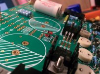
When looking at the original Lehmann BCL SE I see that the 22nf WIMA bypass caps are removed.
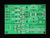
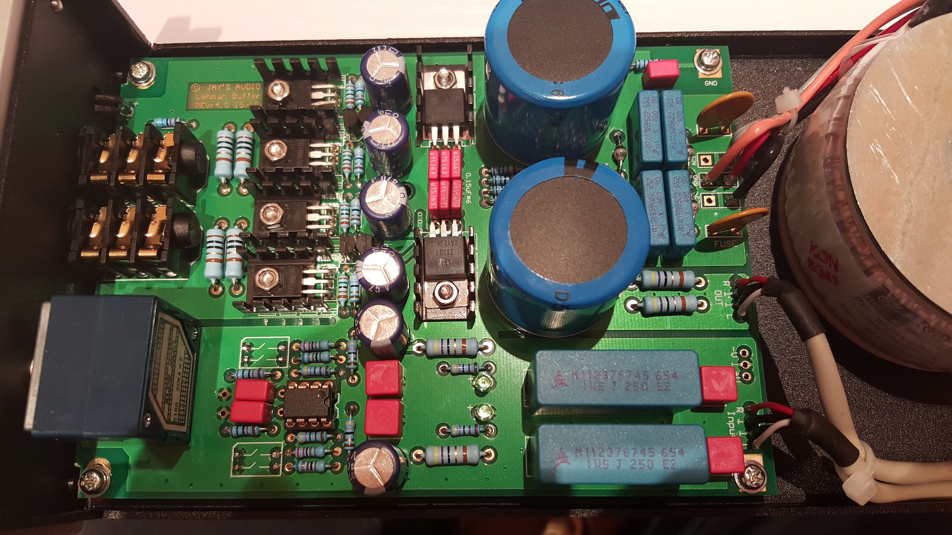
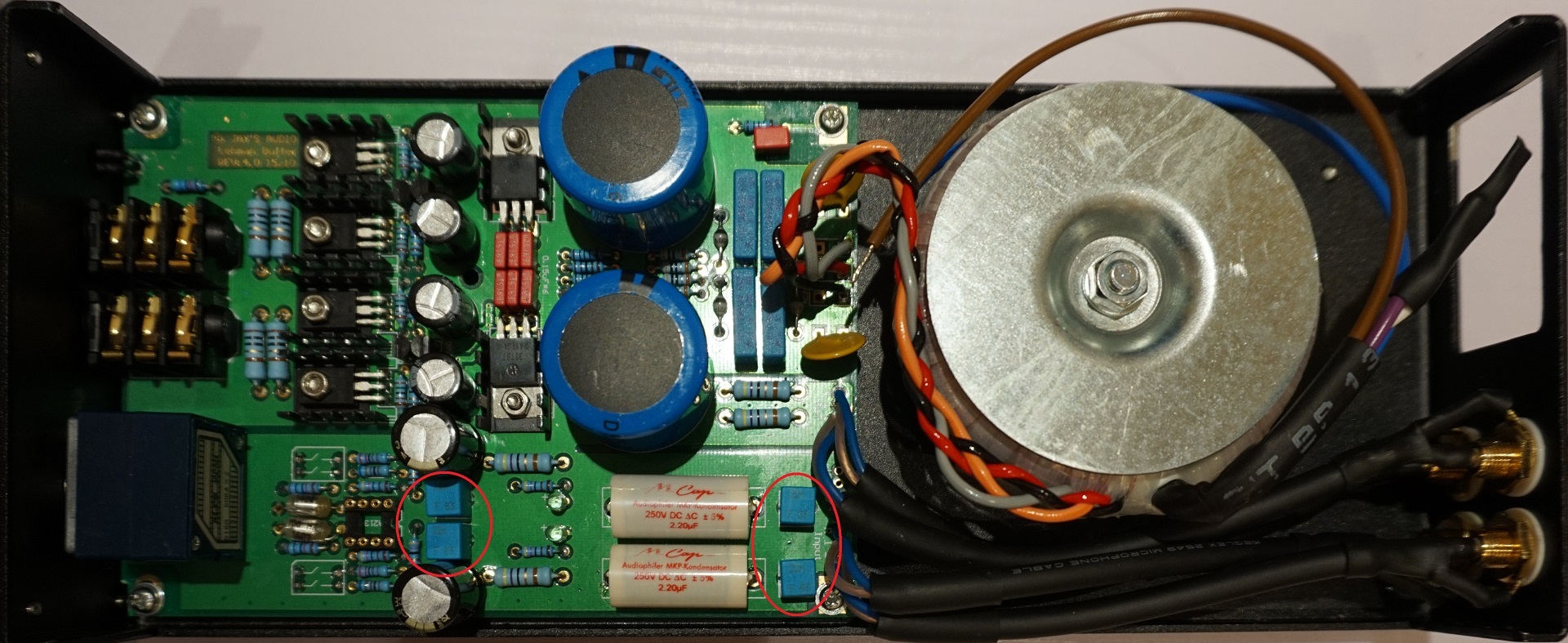
I replaced these with ERO's but I have learned that mostly the best cap is no cap. Capacitors are a necessary to block noise and stuff. My question would be: what can I do with these? Can I just remove them and check if that improves the sound while not creating noise or a big DC offset. I read some people bypassed these with copper wire? I am not sure why. I posted a PCB overview above.
Can someone with a bit of technical knowledge help me out on how and why the caps are there and what to do with them?
I am also doubting if I should upgrade the Vishay BC's for the SE's Mlytics. The Mlytics will cost me about $50 for a pair. Will this investment be returned in significantly better soundquality? I upgraded the transformer to 60VA will this have any influence on my choice for capacitor capacity? Also for the 470uf caps?
And maybe any other weaknesses visible in the circuit and component choice I could look into?
I hope I can get some guidance here. I am open to learning and your advice on these matters
I decided to throw myself on a DIY Lehmann BCL clone. I am a beginner and you should treat me as a fresh one.
I know my soldering and how to work clean and I'm a perfectionist but next to that I have barely the proper knowledge to make right decisions on circuitry.
Lately I have been reading a lot on this forum and other forums to gather more knowledge about different parts and what they are supposed to do. Got me a little wiser but not anything near my goal. That's why I want to share my project here. I hope to get some good tips here about my next few steps.
Since I am currently located in China, I can get my hands on a lot of parts easily and cheap and I ordered a clone PCB and a package of parts that was supposed to be almost identical to the latest version of the original BCL. The components are genuine from RS-components. The tranformer used was a german made BLOCK 40VA instead of the original custom made 30VA.
An externally hosted image should be here but it was not working when we last tested it.
An externally hosted image should be here but it was not working when we last tested it.
An externally hosted image should be here but it was not working when we last tested it.
An externally hosted image should be here but it was not working when we last tested it.
After I put it all together and put it up for the smoke test all worked fine and I was amazed what this machine was capable of even with stock components.
An externally hosted image should be here but it was not working when we last tested it.
An externally hosted image should be here but it was not working when we last tested it.
I decided to upgrade:
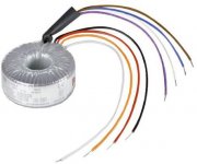
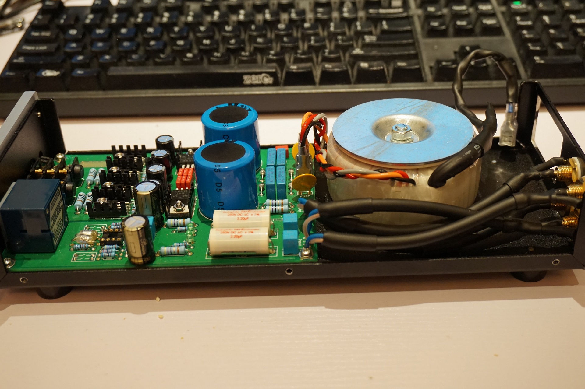
- Replaced transformer. Original 40VA BLOCK to 60VA BLOCK (just fits. Maximum size without any concessions or modifications to case) Also braided the cables for less interference like the original Lehmanns.
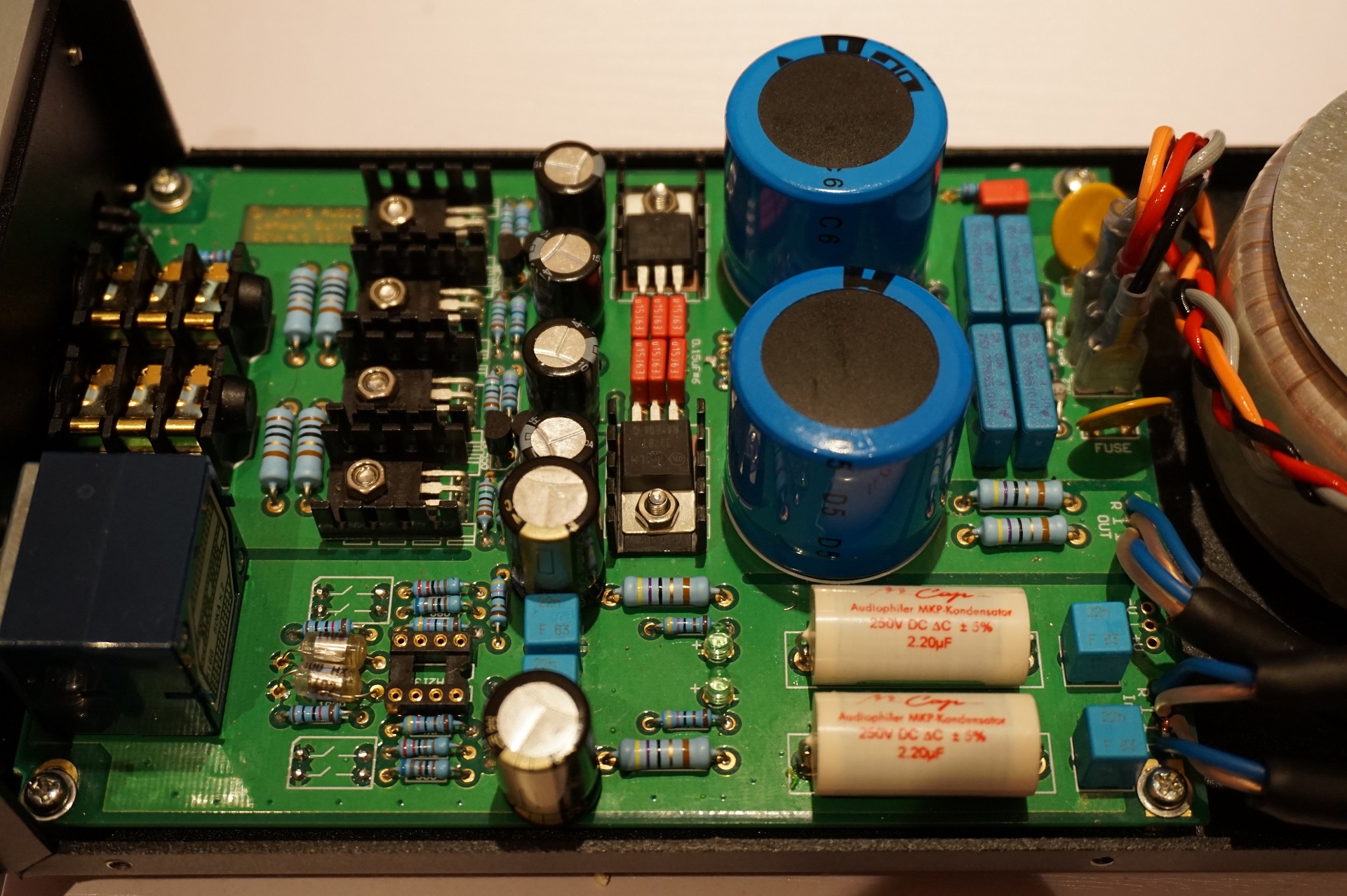
- Replaced input capacitors EPCOS MKP 654 1.5uf 250V with Mundorf MCap MKP 2.2uf 250V (Like Lehmann BCL SE version).
- Replaced all Wima FKP2 22nf 63V caps for ERO MKP 1830 22nf 63V caps.
- Replaced 2 Wima FKP2 100pf 100v 630V caps with LCR 100pf 150V .polystyrene caps. (als have some ERO MKP 1830 for these to try).
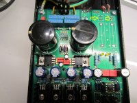
- Replaced 4 Nippon LZX 470uf 25V caps for Panasonic FR 470uf 35V caps.
- Replaced 2 other (opamp) Nippon LZX 470uf 25V caps with Panasonic Pureism 470uf 25V caps.
- Replaced cabling with Mogami Neglex 2549 cables. Soldered to the PCB.
- Replaced opamp with dual discrete opamp OPA111VM with class A mod with 2 x 2.7K resistors. (Still working on a better adapter with less components and soldered.)
An externally hosted image should be here but it was not working when we last tested it.
An externally hosted image should be here but it was not working when we last tested it.
A shielded Schurter powerswitch with fuse is on the way to light this baby up again.
Now I am looking to upgrade a few last things.
When looking at the original Lehmann BCL SE I see that the 22nf WIMA bypass caps are removed.
An externally hosted image should be here but it was not working when we last tested it.
I replaced these with ERO's but I have learned that mostly the best cap is no cap. Capacitors are a necessary to block noise and stuff. My question would be: what can I do with these? Can I just remove them and check if that improves the sound while not creating noise or a big DC offset. I read some people bypassed these with copper wire? I am not sure why. I posted a PCB overview above.
Can someone with a bit of technical knowledge help me out on how and why the caps are there and what to do with them?
I am also doubting if I should upgrade the Vishay BC's for the SE's Mlytics. The Mlytics will cost me about $50 for a pair. Will this investment be returned in significantly better soundquality? I upgraded the transformer to 60VA will this have any influence on my choice for capacitor capacity? Also for the 470uf caps?
And maybe any other weaknesses visible in the circuit and component choice I could look into?
I hope I can get some guidance here. I am open to learning and your advice on these matters
Last edited:
You have linked to the thumbnails rather than the original, big images. Which, btw, you could also add as attachments here so they don't get lost. (Once added, you can copy the link and insert a new image using it.)
Please check whether the PCB is the exact same one as mentioned here, and hence whether it may require the same grounding fixes.
http://www.diyaudio.com/forums/head...z-hum-lehmann-linear-clone-2.html#post4267801
The original parts that you list as replaced all would have been plenty good enough. You won't see me complaining about Nippon Chemicon und WIMA caps. It's not like you've got some Chinese off-brand stuff there.
The Lehmann's Achilles heel is the diamond buffer output stage outside the feedback loop anyway. They probably couldn't get things stable otherwise (at least RJM's Sapphire v1 with similar circuitry apparently often exhibited oscillation issues in GNFB mode) and hence left it at that. Best results are hence expected into mid-high impedance loads.
What sort of headphones do you use anyway?
EDIT: Errr, oops....?! Where'd the first post go?!
I will upload all the pics here.
The PCB is different than the one from your link. This is a 1:1 clone from the Lehmann and revision 4.0. I am in close contact with the shop that cloned this PCB and they are quite serious about that they wanted it to get as close as possible to the original design.
I have no humming problems whatsoever. Everything is stable. Just looking to upgrade it further. Not out of necessity but out of interest and for the learning experience. Trying to understand this little machine.
The WIMA FKP2 caps where supposed to be not very well suited for the signal path. Polystyrene caps would be a better pick for this use? please enlighten me. Thats why I swapped them for ERO's.
The Nichicon's are not bad caps but the Panasonic FR's are better and I had them lying around.
I run the MrSpeakers Mad Dog Pros and DT1770s on it.
Looks like a fun project, on my headphone amp, I have used a snubber on the transformer secondaries, in a CRC arrangement. The values that worked well were a .01uf 600v fkp1 across the leads, and a .1uf 160v polystyrene in series with an 18 ohm R across the leads.
This added a lower noise floor, and better timbre, more bass punch.
Also used some Philips soft recovery diodes that resulted in a similar effect.
The smaller transformers tend to be a bit more noisy it seems, or benefit from doing this.
This added a lower noise floor, and better timbre, more bass punch.
Also used some Philips soft recovery diodes that resulted in a similar effect.
The smaller transformers tend to be a bit more noisy it seems, or benefit from doing this.
I looked up the schematic of this and found its almost identical to the headamp I bought from Taobao last year - this one : https://item.taobao.com/item.htm?sp...135&pvid=642482d1-463e-45bf-a9c8-a0e4a92c4918
A major upgrade can be had from increasing the impedance of the feedback network around the opamp - mine was using a TL072 which has fairly lousy output drive.
A major upgrade can be had from increasing the impedance of the feedback network around the opamp - mine was using a TL072 which has fairly lousy output drive.
Lehmann clones are pretty common, yeah (to the great chagrin of Mr. Lehmann, I might add).
That circuit looks like a case for OPA1642s on adapter boards (FET input, good input impedance linearity). Some further accomodation would be needed for bipolar input types like NE5532 in order to avoid scratchy pot syndrome, though LM4562 may work as-is.
While I'm looking at that part of the circuit, the 10k series resistor between the volume pot and opamp input sure seems excessive. There goes your impedance balance. In high gain, unbalance between the inverting and noninverting input terminals may end up being as high as 12.5k + 10k vs. 680R||4k7 worst-case, which is almost 22k. The OPA2134 datasheet recommends no more than 2k - it's a classic JFET input opamp with the associated input capacitance nonlinearity over common mode swing. I'd swap that 10k for more like 1-2.2k and find some other means of providing RF filtering if need be.
Looks like that was an el cheapo clone then. I'd rather swap out the opamp. The original uses an OPA2134, which should have little difficulty driving 4k7 + 680 ohms worst-case.A major upgrade can be had from increasing the impedance of the feedback network around the opamp - mine was using a TL072 which has fairly lousy output drive.
That circuit looks like a case for OPA1642s on adapter boards (FET input, good input impedance linearity). Some further accomodation would be needed for bipolar input types like NE5532 in order to avoid scratchy pot syndrome, though LM4562 may work as-is.
While I'm looking at that part of the circuit, the 10k series resistor between the volume pot and opamp input sure seems excessive. There goes your impedance balance. In high gain, unbalance between the inverting and noninverting input terminals may end up being as high as 12.5k + 10k vs. 680R||4k7 worst-case, which is almost 22k. The OPA2134 datasheet recommends no more than 2k - it's a classic JFET input opamp with the associated input capacitance nonlinearity over common mode swing. I'd swap that 10k for more like 1-2.2k and find some other means of providing RF filtering if need be.
Looks like that was an el cheapo clone then.
Not entirely as the case is a thing of beauty and the opamp was in a ceramic package. But it was only 368RMB fully boxed and ready to roll (not a kit) so yeah it was definitely cheap.
I'd rather swap out the opamp. The original uses an OPA2134, which should have little difficulty driving 4k7 + 680 ohms worst-case.
Each to their own. Dynamics I've found improve no matter what the opamp so I nowadays choose the cheapest that gives the sound I'm looking for.
I still have no answer for what to do with the input caps.
I've managed to get the pictures working:


I've managed to get the pictures working:
Attachments
-
 TB2DoWIcpXXXXXPXXXXXXXXXXXX_!!17455497.jpg379.6 KB · Views: 2,467
 -
 TB2whpCbXXXXXc.XXXXXXXXXXXX_!!17455497.jpg298.3 KB · Views: 2,366
 -
 R7529268-01.jpg44.9 KB · Views: 2,317
 -
 TB2BxBWfpXXXXbCXpXXXXXXXXXX-17455497.jpg222.1 KB · Views: 2,340
 -
 TB2RrtqipXXXXbDXpXXXXXXXXXX_!!17455497.jpg229.7 KB · Views: 2,400
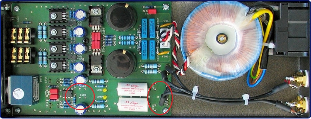
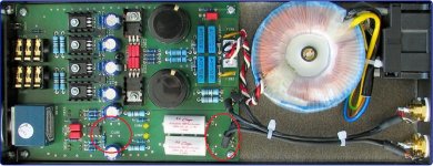
This is what the original build was like
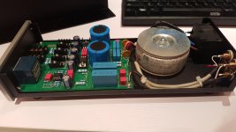
I changed it to the following:
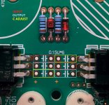
But now I'm stuck. I know the original Lehmann SE did way with the bypassing input caps (originally Wima FKP2, mine ERO 1830). But I'm not sure about this. Can I just remove them and give the system a test run and check DC offset? The original SE also has no Wima FKP2 caps between the 470uf caps near the opamps. I would love to test if removing them would improve sound quality. Can I just remove them?
I changed it to the following:
But now I'm stuck. I know the original Lehmann SE did way with the bypassing input caps (originally Wima FKP2, mine ERO 1830). But I'm not sure about this. Can I just remove them and give the system a test run and check DC offset? The original SE also has no Wima FKP2 caps between the 470uf caps near the opamps. I would love to test if removing them would improve sound quality. Can I just remove them?
Attachments
-
 bypass.jpg180.4 KB · Views: 2,290
 -
 marked_inputcaps.jpg500.2 KB · Views: 2,391
 -
 marked_SE_inputcaps.jpg189.2 KB · Views: 2,334
 -
 DSC05691.JPG704 KB · Views: 2,462
 -
 DSC05692.JPG620 KB · Views: 2,411
 -
 20151228234414-433606379_20151228_234414.jpg799.2 KB · Views: 2,523
 -
 20151228234350-1210287540_20151228_234350.jpg850.7 KB · Views: 2,352
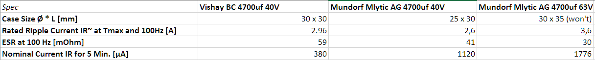
I would also like to know what your opinion is about switching the Vishay BC 4700uf caps for the Mundorf Mlytic 4700uf caps.. They are not really cheap. First want an opinion on if it would be worth the investment.
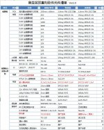
Specs:

The Vishay BC is already supposed to be quite good and better than Nichicon and Elna for this function. Can anyone maybe comment on this?
Will it be worth to upgrade? The Mlytics cost 150 yuan ($22) each and the Vishay's which I already have are about one third of their price at $7,50 each. Is it hype or did Lehmann really know what he was doing picking these caps? And what will improve in the sound?
Specs:
The Vishay BC is already supposed to be quite good and better than Nichicon and Elna for this function. Can anyone maybe comment on this?
Will it be worth to upgrade? The Mlytics cost 150 yuan ($22) each and the Vishay's which I already have are about one third of their price at $7,50 each. Is it hype or did Lehmann really know what he was doing picking these caps? And what will improve in the sound?
Attachments
Last edited:
I sincerely disagre with your choices...
- Replaced input capacitors EPCOS MKP 654 1.5uf 250V with Mundorf MCap MKP 2.2uf 250V (Like Lehmann BCL SE version).
- Replaced all Wima FKP2 22nf 63V caps for ERO MKP 1830 22nf 63V caps.
- Replaced 2 Wima FKP2 100pf 100v 630V caps with LCR 100pf 150V .polystyrene caps. (als have some ERO MKP 1830 for these to try).
- Replaced 4 Nippon LZX 470uf 25V caps for Panasonic FR 470uf 35V caps.
- Replaced 2 other (opamp) Nippon LZX 470uf 25V caps with Panasonic Pureism 470uf 25V caps.
- Replaced opamp with dual discrete opamp OPA111VM with class A mod with 2 x 2.7K resistors. (Still working on a better adapter with less components and soldered.)
NCC LZX are incredibly good and neutral sounding capacitors, Panasonic FR are, IMHO, worse here.
FRs are good caps but they sound somewhat 'bigger' than reality and reduces soundstage.
On the opamp, though, higher ESR audio caps give better results, I never tried Pureisms, I've used Silmics II black/gold 100uF 25V.
ERO KP1830 are really good caps but no better than FKP2, the only difference is that KP1830 are a tiny bit more neutral, in this case I would have kept the FKP2.
The polystyrene caps are a good choice but I prefer Amtrans AMCH.
When looking at the original Lehmann BCL SE I see that the 22nf WIMA bypass caps are removed.
There are two couples of them, I would keep the ones near the opamp, the opamp decoupling on the PCB is really poor (long traces).
Regarding the other two they're used as bypass for the input caps and they're not needed if you use better input caps or can be used to short input caps if you don't need DC blocking.
I don't use input caps at all here, the improvement is stunning.
I am also doubting if I should upgrade the Vishay BC's for the SE's Mlytics. The Mlytics will cost me about $50 for a pair. Will this investment be returned in significantly better soundquality?
Absolutely!
Mundorgf AGs are incredible.
BCs are incredibly good for the price but the Mundorf are on another league.
You can also improve the PS with two simple mods:
- Replace the LM317 voltage setting resistors with zeners (BZX85 13V)
- Replace LM317 C ADj with 10uf 35V Silmics II Black Gold.
Also replace all signal resistors with Vishay/Dale RLR07 or PTF56.
I've also used some Vishay VSRJ bulk metal foils but PTF56 will be quite as good.
Attachments
Both, basically. BCL clones usually stick with the original schematic, a version of which a quick Google Images search should turn up (like here), so you can possibly follow the suggestions better. While some builders take their liberties when it comes to parts choices, yours seems to be a particularly close clone, so I imagine you've got a (probably TI branded) OPA2134 in there, right? If there are any questions WRT suggestions, please do ask.So the thread took a lift off. I am a bit confused about if the tips are pointed towards my project or the other one.
I am not sure why Lehmann did away with the two 22n/63V bypass caps at the opamp (that's the one you meant, right?). Maybe they found them to be useless or even detrimental. 470µ + 22n is not a terribly good combination actually, the very big difference in values bears the risk of a parallel resonance created by electrolytic parasitic inductance plus film capacitance. That means your rail decoupling actually goes high impedance in the affected frequency range, and if your circuit happens to be relying on low impedance just there, it may start oscillating.
Taking some cues from LM3886 decoupling, I'll suggest using some 22 µF / 35 V Oscons (35SEPF22M+TSS) instead of the 22n FKP2s, polarity observing. These are 6 mm dia. vs. the WIMAs' 7.2x7.2 mm, so should fit easily when adapting the lead spacing. Please never bend the leads right where they are leaving the cap, but rather a few millimeters away, in order to avoid damage. Try to keep lead lengths to a minimum anyway.
For an indication of up to what sort of frequency your rail decoupling should remain useful, you can use amplifier bandwidth. OPA2134 has a nominal GBW of 8 MHz, minimum gain is a bit over 3, so that leaves a good 2.5 MHz. Load impedance is quite high, which should relax requirements a bit.
The 4700 µF caps are just fine. There is precious little to be gained from boutique parts over good-quality industrial fare here, in fact I would assume the mass-produced ones would be of more consistent quality and more strictly tested.
It rarely ever makes sense to try and upgrade parts in equipment that uses good-quality components to begin with, unless you like the sound of placebo (not the band). This approach makes the most sense with gear that is basically well-designed but then underwent cost-cutting. A prime example would have to be Behringer's xxx2496 series devices (DEQ, DCX etc.), where it was found that the use of a number of small ceramic capacitors in the signal path (seemingly not NP0 but rather some crummy dielectric, even down below 1 nF) led to significantly worsened high-frequency distortion performance (as in ~20 dB). Or the fun to be had when unsuited caps are used in the output filter of a Class D amp.
In case of the BCL, the limitations are related to topology and part value choices, not parts quality IMHO.
Last edited:
Thnx for all the help. I am trying to look into the choices suggested here.
What capacity are your Amtrans AMCH.caps with the opamp?
I will just remove the input ERO caps and see if it makes a difference.
Replacing the resistors around the opamp all with the same values as the originals I assume?
I am also looking into the OSCONS.
Ano about the ZENER diodes. I can only find black ones on taobao.. I see they are supposed to be red ?
What capacity are your Amtrans AMCH.caps with the opamp?
Same value as the originals, 100pF if I remember correctly
I will just remove the input ERO caps and see if it makes a difference.
Remember to remove also the bypasses and use their pads to short.
Let us know.
")
Replacing the resistors around the opamp all with the same values as the originals I assume?
Absolutely.
I am also looking into the OSCONS.
You will have some difficult time... I still have to find one that sounds as it should.
Ano about the ZENER diodes. I can only find black ones on taobao.. I see they are supposed to be red ?
Probably pictures are generic diodes ones, BZX85 from NXP and Fairchild are red glass diodes.
Buy some more than 2 so you can match them, it will ensure a lower DC offset on output.
The same (matching) is valid for all parts (resistors, transistors, film capacitors)
Remember to remove also the bypasses and use their pads to short.
Let us know.
What do you mean by this?
And I am looking for the Vishay Dale resistors and they only come in 1/4W 1/2W and 1W. 1/2W will be fine I guess?
You will have some difficult time... I still have to find one that sounds as it should.
What would you suggest then? Is this why you have chosen to lower the caps near the opamp to the ELNA SILMIC II 100uf? To match the Wima caps better? Like sgrossklass because of the size difference?
What do you mean by this?
After removing both coupling caps (the main 2.2uF one and the .22 bypass) you must restore continuity. To do it youl'll need to solder a piece of wire to the pads of one of the two capacitors position (AKA short it).
BTW verify before that your source/preamp have DC blocking caps.
And I am looking for the Vishay Dale resistors and they only come in 1/4W 1/2W and 1W. 1/2W will be fine I guess?
You'll need 1/4W for RLR07 or 1/8W for PTF56.
What would you suggest then? Is this why you have chosen to lower the caps near the opamp to the ELNA SILMIC II 100uf? To match the Wima caps better? Like sgrossklass because of the size difference?
Simply size and BTW 100uF are enough for the job, IMHO.
Attachments
- Status
- This old topic is closed. If you want to reopen this topic, contact a moderator using the "Report Post" button.
- Home
- Amplifiers
- Headphone Systems
- [Headamp] upgrading a Lehmann BCL clone