Hi, I finally gathered my courage and built myself a headphone amplifier. Since I haven't got any experience of electronics and this was my first build, I have been reading a lot on the net about the Cmoy amp and op amps in general. But there is still one thing I don't fully understand.
This is the role of the input resistor (R2) in determining the input impedance of the op amp. Below is the schematic for my amplifier. Since it is using a JRC4556AD, which has an input bias current of 50 nA, I decided to go with 10k as R2 to get the DC offset low.
With R2 at 10k the DC offset is 0.5 mV on both channels with unity gain and 1.5 mV with a gain of roughly 3. The build was successful on other accounts too, the power supply pins give an even split on the voltage (I'm using 2 x 9 V with real ground as Grado RA-1) and it sounds clean without any hiss.
I could have built my amp with just unity gain, since I mostly use it just as a means to control the volume, but I built it with a gain switch, just in case I need gain some day. My solution for the gain switch might be a bit unconventional, the other solutions i saw involved changing the value of R3.
So, the question remains: does R2 set the input impedance for the op amp? Have I gone too low with R2 in that case? Is this going to be harmful for the op amp or the source (which is a X-FI sound card)? NJM4556 data sheet gives the chip an input impedance of 0.3 M ohm minimum and 5 M ohm typical.
I know that R2 and the input cap form a low pass filter and that is why I went with a 2.2 uF cap to keep the corner frequency low.
The op-amp wont be harmed by any value of R2, even replacing it with a wire link.
The DC 'impedance' of the circuit is always 10k (the pot). The AC input impedance of the circuit as a whole is a variable and depends on the setting of the volume control. At maximum volume it has an impedance of 5k (because the resistors appear in parallel at AC as they are coupled via the cap). At minimum volume it has an AC impedance of 10k (just the pot). At all other positions, the DC impedance is always 10k, the AC impedance varies.
The DC offset is only at a minimum when both the - and the + inputs see the same DC resistance whcih means you will always see a jump in offset as you operate the gain switch.
Thanks for the information, Mooly! I kind of wondered about the R2 value in Chu Moys amp, and I had a hunch it might have more to do with keeping the input cap smaller. But as i already confessed, my knowledge about electronics is pretty limited, so I had to get some clarification to the issue, since I found mixed information about the role of R2, some claiming it sets the input impedance and some saying it is there for the low pass filter.
R2 and the cap form the high pass filter, around 7Hz in this case.
Having R2 low in comparison to the pot has another effect as well and that is that it changes the 'law' of the pot. This is a recognised trick to make a linear pot behave as if it had a log law although the values here don't quite achieve that.
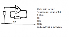
The way to get minimum DC offset is to AC couple the feedback return as well (the 470 ohm) and to set R4 to equal R2. If R4 were 10k and the 470 ohm switched out of circuit then you have unity gain. Switch the now AC coupled 470 ohm into circuit and you have gain. Of course with R4 being 10k then you need to scale the 470 ohm to 4k7.
Having R2 low in comparison to the pot has another effect as well and that is that it changes the 'law' of the pot. This is a recognised trick to make a linear pot behave as if it had a log law although the values here don't quite achieve that.
The way to get minimum DC offset is to AC couple the feedback return as well (the 470 ohm) and to set R4 to equal R2. If R4 were 10k and the 470 ohm switched out of circuit then you have unity gain. Switch the now AC coupled 470 ohm into circuit and you have gain. Of course with R4 being 10k then you need to scale the 470 ohm to 4k7.
Ah, so unity gain works even if I leave R4 out of the circuit. I wasn't sure about that, so that was the reason why I decided to get the gain (or unity gain) with switching between R3 values. Originally I got the idea from my 1st circuit where I had R2 at 100k and R3 at 120k. There I got (near) unity gain with setting R4 for to 470 ohm. I got the idea from Nwavguys blog, where he tested the Ebay Cmoy.
And I mixed up the low pass and high pass in the filter.
And I mixed up the low pass and high pass in the filter.
It would be better to hard wire R4 in place and switch a shorting link across it in and out of the circuit.
You don't want to ever open circuit the NFB loop.
I got the circuit built using 10 K resistors for R2 and R4. I managed to find a 1 K log pot, so I used it instead of the 10 K I already had. For R3 I went with 2,6 K giving me a gain 4.8. With R3 switched off from the circuit (unity gain), DC offset is barely measurable with my DMM, 0.01 mV. With high gain i get 1.5 mV.
Thank you once more for the help!
Thank you once more for the help!
Thank you once more for the help!
Thanks for the update, and I'm pleased you have it all working. (I must have missed your reply yesterday)
Sgrossklass, I'll keep that in mind, if I ever get me any other audio equipment. I knew X-Fi uses a 4556, too bad it has such a high output impendance. My main goal with the project was to lower it, and a cmoy seemed a good and simple way to achieve that goal. My headphones are AKG 601s and to me it seems the bass got tighter with the cmoy. Other than that the amp sounds neutral and transparent, so I'm very pleased with the end result.
The second goal was to get a convenient way to adjust the volume, and I truly appreciate that I can do it by turning a volume knob instead of dragging sliders with a mouse.
Oh, and here is the final product, I used the only box I had available in the house. It is the box my watch came in, and it happened to have pretty much ideal dimensions for the project. The lid closes with a button, so it easy to replace the batteries, when the time comes. The front switch is power and the rear one controls the gain, down for unity and up for high gain.
Just noticed that your schematic shows two 100 nF bypass caps only - is that how you built it? Keep in mind that batteries as chemical devices tend to be notoriously slow and are not likely to have low source impedance at medium to high frequencies, so you would do well in adding the standard 2x 220 µF (or thereabouts) bypass capacitors. If they're already there, ignore this.
The X-Fi should have an output impedance in the 33 ohm vicinity if memory serves and K601s are not too impedance-critical (about 125 ohms min, 150 max), so from a quick calculation the difference would be expected to be just about detectable (0.3 dB is about the limit).
BTW, since you have a decent soundcard, this may be a good opportunity to obtained a good splitter cable and take some measurements of your creation with RMAA, both unloaded and with headphones connected. You will see some ground loop noise, but it shouldn't be too bad if you can keep the loop area (!) of the connection output --> amp --> splitter --> input as small as possible.
Last edited:
The schematic didn't show the power supply section of the amp, I have two 220uF caps there and those 100 nF caps are soldered pretty much directly to the IC socket pins. I could install RMAA and I think i have a 3.5mm splitter cable somewhere, if I can find among all the stuff in the drawers. I just need figure out how to use the software, I think most of them are run using the cards own input for the measurements.
Ok, I found the cables. I ran the tests with the card output set to 100% and the amp at unity gain. I didn't dare to use the high gain, I guess it would clip. Here are the results. If they are good or bad, that I'm not capable of saying. I admit I don't fully understand all the numbers.


Right-click number to display the corresponding graph.
THD and FR look promising, noise and IMD are a bit low but I guess inspection of the graphs would show all kinds of ground loop crap. THD (swept) is taken with a 20 kHz limit by default though you can disable that somewhere in prefs. If you are using default settings, make sure both record and playback device are set up the match the sample rate and bit depth in RMAA; I think automagic setting is only possible when using ASIO.
THD and FR look promising, noise and IMD are a bit low but I guess inspection of the graphs would show all kinds of ground loop crap. THD (swept) is taken with a 20 kHz limit by default though you can disable that somewhere in prefs. If you are using default settings, make sure both record and playback device are set up the match the sample rate and bit depth in RMAA; I think automagic setting is only possible when using ASIO.


These are some excellent results for a little cMoy. I guess the IMD graphs will show it breaking a bit of a sweat when loaded as the numbers would imply, but it still is rather good performance.
You can test the high gain setting if you decrease output volume accordingly. Try about 40% for a start, and optimize level with "Adjust playback/recording" enabled.
You can test the high gain setting if you decrease output volume accordingly. Try about 40% for a start, and optimize level with "Adjust playback/recording" enabled.
- Status
- This old topic is closed. If you want to reopen this topic, contact a moderator using the "Report Post" button.
- Home
- Amplifiers
- Headphone Systems
- Cmoy input resistor value?