Hello everyone.
Sorry for my bad english, not native speaker")
As you know there are plenty devices with biased OPAMP to class A.
But how about biasing hi current opamp (like AD8397 or THS6012) to class A (full range)?
Is it really worth it (in term of sound quality) ?
How about thermal disspation?
I saw plenty biased opamp, but they are only voltage stage with additional hi current buffer, so thery biased with some small currents.
Am I right, for full scale bias of hi current OPAMP there will be needed something about ~ 100mA (maybe more depending of power supply and load).
Maybe you know some good JFET that can handle that current demands?
I found something like this, but maybe there is some better choice instead of this :
BSR57,215 NXP Semiconductors | Mouser
Regards.
Sorry for my bad english, not native speaker
As you know there are plenty devices with biased OPAMP to class A.
But how about biasing hi current opamp (like AD8397 or THS6012) to class A (full range)?
Is it really worth it (in term of sound quality) ?
How about thermal disspation?
I saw plenty biased opamp, but they are only voltage stage with additional hi current buffer, so thery biased with some small currents.
Am I right, for full scale bias of hi current OPAMP there will be needed something about ~ 100mA (maybe more depending of power supply and load).
Maybe you know some good JFET that can handle that current demands?
I found something like this, but maybe there is some better choice instead of this :
BSR57,215 NXP Semiconductors | Mouser
Regards.
Thermal dissipation will be a big issue for the AD8397 as its limited to around 0.8W with no heatsink @25oC. THS6012 can dissipate more (almost 6W) but needs its thermal pad connecting to a decent heatsink.
How much bias current you need depends on your desired SPL and your phones impedance.
A JFET to do the biassing is a little inflexible, especially one limited to just 250mW dissipation, why not use a two transistor current source? The transistor dissipating the real power can then have an appropriate heatsink.
Thank you for answer.
Let me think
I use 10K pot (or unbuffered PGA2311), typical DAC Vrms is 2V or 2.5V.
I'll never use headphones with lower impedance than 16 ohm, so I want full scale bias.
But I'm "new in town" could tell me how to do it properly with JFET or BJT's?
My power supply will be symetrical 12V or 15V depending on chips demands.
I currently use chip with thermal disspation rated at 1.87 W@25C.
This is SO8 package, but I have some spare (small) heatsink that I can put on top.
I solder thermal pad directly to my four layer board, TPAD is connected to inner and outerlayer with 12x 0.3mm via.
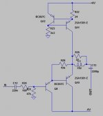
Instead of slapping a CCS at the output of the opamp, jcx has shown another method, for example here: http://www.diyaudio.com/forums/chip-amps/108076-parallel-tpa6120.html#post1297538
Driving low impedance phones means you don't need any gain - just a buffer. That can be built from discrete transistors - I use a darlington arrangement - and then the current source is the load for the buffer. I'll put up a schematic to show what I mean. Incidentally you'll want a lower supply than 12V symmetrical or you'll just waste power - I suggest 6V symmetrical.
<edit> Very rough draft schematic added.
<edit> Very rough draft schematic added.
Attachments
Last edited:
The current source (if you just want to use that part) is the two transistors at the top of the schematic. Normally you'll use an NPN variant of that (where the transistors swap sex : BC847C and 2SC1381) connected to the -ve rail.
Ok, looks familiar to JFET's cascode.
Could you tell me how much current will be needed to "name it" full range bias?
As I mentioned above I have symetrical 15V power supply (1,5A per rail).
Full range will be better for me, I very often change my headphones and testing new pairs.
I'll have to make an assumption for deciding on the bias you'd need.
Assuming your maximum power output is 100mW (i.e. you're not driving planars) then for 16ohms this is a peak current of 80mA. That'll be the level of bias you need to keep the amp in classA. The example I've shown has the current setting resistor (24ohm) set around 25mA. So you should reduce it to 8.2R and the 3k3 should also be reduced to 1k for a 6V supply. With 15V you should use 2k7.
I'd not advise going above 80mA with the transistor I've specified as its max continuous Ic is 100mA.
For planars I think a dedicated design is advisable because you'll be wanting upwards of 500mW right?
Driving a 25ohm load when the supplies are 15V means the peak current is going to be around 600mA (for full rail swing). 440mA suggests you're not getting rail-to-rail output - but do you have heatsinking capable of handling 15*0.44 = 6.6W on your opamp?
Driving a 25ohm load when the supplies are 15V means the peak current is going to be around 600mA (for full rail swing). 440mA suggests you're not getting rail-to-rail output - but do you have heatsinking capable of handling 15*0.44 = 6.6W on your opamp?
For planars I think a dedicated design is advisable because you'll be wanting upwards of 500mW right?
Driving a 25ohm load when the supplies are 15V means the peak current is going to be around 600mA (for full rail swing). 440mA suggests you're not getting rail-to-rail output - but do you have heatsinking capable of handling 15*0.44 = 6.6W on your opamp?
Package can disspate almost 2W itself.
There is also a solid ground plane (4 layer board) and I can put heatsink like this (I know it small).
ICK SMD A 5 SA (look at Farnell website).
So what do you think? It will survive?
I choose opamp that is able to working with higher ambient temp (there is two version named commercial and industrial, I choose industrial).
I can't understand your question - the current you must provide is determined by how loud you want the 'phones to play. If you're content with 1W peak then for 25ohms that's 200mA peak. If you reduce your supply (say 7V symmetrical) then with appropriate heatsinking your THS6012 will be able to handle the dissipation in pure classA.
Ok, ok.
Maybe I should ask diffrent question.
Is this are really worth it? To bias hi current opamp to class A?
I saw some little devices like Geek Out that are in class A so I was curious how about bigger devices and biasing advantages.
Thank you for help and quick answers.
And once again sorry for my poor english.
- Status
- This old topic is closed. If you want to reopen this topic, contact a moderator using the "Report Post" button.
- Home
- Amplifiers
- Headphone Systems
- Biasing OPAMP to class A [Hi Current type]