I did get a PM about the breakout I have. I am going to start a new post in this forum with the Eagle files for that breakout. You can have them fabbed through OshPark for $3.60 for 3 breakouts with free shipping. I have run many of these boards through countless tests with various configurations and have had no problems at all. Look for the post in this forum with all files.
I did get a PM about the breakout I have. I am going to start a new post in this forum with the Eagle files for that breakout. You can have them fabbed through OshPark for $3.60 for 3 breakouts with free shipping. I have run many of these boards through countless tests with various configurations and have had no problems at all. Look for the post in this forum with all files.
http://www.diyaudio.com/forums/headphone-systems/278373-tpa6120-breakout-free-design-files.html
In case google indexes this post and we can't find the breakout post
")
Hi !I'm a little afraid to run it! some parts got VERY hot during a few minutes time and without a design doc, I can't know this is was competantly designed or not.
I hooked up the scheme, with the power transformer must be submitted no more Uxx -14.5v,
all transistors and resistors 47Ohm lukewarm, we can say - cold.
But as soon as I applied to the circuit from the transformer Uxx 16-17v all begins to get warm! so I conclude - the supply voltage of the transformer at no more than 14.5 v
Ampr is working properly, so as to play 61202a.
questions - ask ..... answer!
how much headroom is there so that the regulator stays in regulation? sometimes if you lower the input voltage, sure, the differential creates less heat. but that also means that if the source dips (brown out) you are not in regulation anymore. if you have to 'under volt' a power supply to avoid it buring itself up, I question the quality of such a design.
and for this chip, I see absolutely no reason for it. its generating heat for no good reason and that really annoys me.
I'm not really enthused about having to worry about input voltage being 2 volts higher and things getting really hot.
to contrast, I'm using a TI eval board (so its 'idiot proof', lol) that has a pos and neg low noise reg chip and a few passives, and you can throw tons of voltage into it and still have it run very cool, very low noise and I'm using it with the 6120 phones amp chip and things seem pretty good! I wished the ebay board would have just gone that route instead of the 'burn itself up' style of design. sigh...
TPS7A30-49EVM567
tiny little chips and they seem to throw off no heat that I can notice. keep your finger on it and you don't even notice anything. its that good. I think I've put in 24v and set the regs to 8v (I was using a chip that had a max rail of dual-8, not the usual dual-12). and even with that differential, it was fine and its been running for at least 2 years, 7x24, now.
so, I guess I don't see the point, myself, of wanting to debug or get this ebay board working. just seems like a stupid design and to waste that kind of heat for no damned good reason seems absurd to me.
if others want to work on this, that's fine, but for me, I have no interest in that kind of design. I really hate hot-running things (in case you didn't guess, lol) and especially when its not at all necessary.
yes design power scheme - a very exotic,
it is more suitable to the driver of the motor or something else, but it is the place to be!
It could easily take 137 and 337 ..... but - is Chinese!
When submitting a transformer 14.4V voltage regulator can be set from 12v to 15v, I put 13 in. circuit works.
it is more suitable to the driver of the motor or something else, but it is the place to be!
It could easily take 137 and 337 ..... but - is Chinese!
When submitting a transformer 14.4V voltage regulator can be set from 12v to 15v, I put 13 in. circuit works.
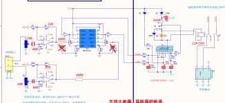
I purchased a similar amp on eBay and received it yesterday. Attached is a picture of the amp. I requested a schematic from the seller and they provided one to me. I'll try to attach the original schematic (chinese) and a version that I translated online.
Attachments
Last edited:
I purchased a similar amp on eBay and received it yesterday. Attached is a picture of the amp. I requested a schematic from the seller and they provided one to me. I'll try to attach the original schematic (chinese) and a version that I translated online.
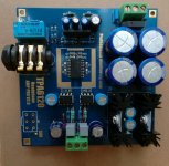
I bought this same board, but in kit form knowing I'd do some mod while assembling it. The seller provided with the same schematic as what you have posted. The picture was taken before installing the volume pot and the heat sink for the TPA6120.
Below is the mods I did just in case there is interest:
1) Problem: relay in the kit is of wrong voltage rating (5V) and would cause both the relay and resistor R1 to heat up. Unlike indicated in the schematic, the relay draws current from the non-regulated supply (that could be as high as 24V) in the PCB layout.
Mod: Changed the relay to a 12V rating one and R1 to 910R. This reduces the coil current to 1/3 that otherwise case. Heating up no more.
2) Problem: NE5534 is spec-ed for stable operation at gain of minimum 3x, yet the gain as in the schematic was set to 2x, and they put a 1000pF cap right at the NE5534 output to GND to try to seemingly "stabelize" it.
Mod: Changed the gaing setting resistors (10K SMD on the bottom side) to 22K to set the gain to slightly higher than 3x, removed the 1000pF caps, cut the PCB traces and insert a 50R resistor between NE5534 output and TPA6120 inout.
3) Problem: Volume pot was part of NE5534 DC bias circuit, and therefore, it can have ill effects, A -- it can introduce wiper noise and B -- it can affect the DC offset at the amplifier output.
Mod: cut the PCB traces and re-wired the DC-blocking capacitors (missing from the supplied schematic) to have them AC-couple the volume pot to NE5534 input, and the volume pot re-wired directly to the signal input terminals. Replaced the two regular polar type electrolytic caps with non-polar type for signal coupling. The 10K resistors at the non-inverting input of NE5534 are changed to 6K8 to cancel out the DC offset from the input bias current of NE5534.
4) Problem: Copper foil for the TPA6120 thermal pad was floating
Mod: short it out to GND
5) Problem: the supplied volume pot is 50Kohm, a bit too high for the NE5534 gain stage that has an input impedance under 10Kohm.
Mod: replace with 10K volume pot.
The power transformer that I use is a 10VA 2x15Vac toroid that puts out a no-load voltage about 18Vac @ 122Vac mains. The non-regulated DC is about +/-24V at idle.
Attachments
I bought this same board, but in kit form knowing I'd do some mod while assembling it. The seller provided with the same schematic as what you have posted. The picture was taken before installing the volume pot and the heat sink for the TPA6120.
Below is the mods I did just in case there is interest:
1) Problem: relay in the kit is of wrong voltage rating (5V) and would cause both the relay and resistor R1 to heat up. Unlike indicated in the schematic, the relay draws current from the non-regulated supply (that could be as high as 24V) in the PCB layout.
Mod: Changed the relay to a 12V rating one and R1 to 910R. This reduces the coil current to 1/3 that otherwise case. Heating up no more.
2) Problem: NE5534 is spec-ed for stable operation at gain of minimum 3x, yet the gain as in the schematic was set to 2x, and they put a 1000pF cap right at the NE5534 output to GND to try to seemingly "stabelize" it.
Mod: Changed the gaing setting resistors (10K SMD on the bottom side) to 22K to set the gain to slightly higher than 3x, removed the 1000pF caps, cut the PCB traces and insert a 50R resistor between NE5534 output and TPA6120 inout.
3) Problem: Volume pot was part of NE5534 DC bias circuit, and therefore, it can have ill effects, A -- it can introduce wiper noise and B -- it can affect the DC offset at the amplifier output.
Mod: cut the PCB traces and re-wired the DC-blocking capacitors (missing from the supplied schematic) to have them AC-couple the volume pot to NE5534 input, and the volume pot re-wired directly to the signal input terminals. Replaced the two regular polar type electrolytic caps with non-polar type for signal coupling. The 10K resistors at the non-inverting input of NE5534 are changed to 6K8 to cancel out the DC offset from the input bias current of NE5534.
4) Problem: Copper foil for the TPA6120 thermal pad was floating
Mod: short it out to GND
5) Problem: the supplied volume pot is 50Kohm, a bit too high for the NE5534 gain stage that has an input impedance under 10Kohm.
Mod: replace with 10K volume pot.
The power transformer that I use is a 10VA 2x15Vac toroid that puts out a no-load voltage about 18Vac @ 122Vac mains. The non-regulated DC is about +/-24V at idle.
Awesome! Thanks for posting your mods.
How did you solder the PowerPad, reflow or careful hand soldering?
I'm going to try rolling some other opamps in place of the NE5534's, especially since you noted the mismatched gain.
Sent from my iPhone using Tapatalk
....soldering the PowerPad of TPA6120: clean the center pad on PCB with isopropyl alcohol, tin with solder, make sure solder flows to and wets the other side through the vias, wick off all solder, make sure all vias in the pad remain open. Tin the power pad on the chip and wick off. Level the pcb on a table vise so that you can access the bottom side where the power pad is. Apply gel flux to the center pad and sit the chip on PCB, use a massive possible tip available to the iron and set iron temp at 350C, with plenty solder on the tip heat the center pad from bottom side for 10 seconds or longer. The capillary action will draw solder to the top side and make joint with the ship's power pad.
Tinning the board is not needed if a board had hot air leveled tin-lead finish. But this particular board came with gold finish and one would wonder what "gold" they put on this cheapo, and that's why tinning. I found the solder-ability of this gold-finished PCB mush worse than one with tin-lead finish.
Tinning the board is not needed if a board had hot air leveled tin-lead finish. But this particular board came with gold finish and one would wonder what "gold" they put on this cheapo, and that's why tinning. I found the solder-ability of this gold-finished PCB mush worse than one with tin-lead finish.
I bought this same board, but in kit form knowing I'd do some mod while assembling it. The seller provided with the same schematic as what you have posted. The picture was taken before installing the volume pot and the heat sink for the TPA6120.
Below is the mods I did just in case there is interest:
1) Problem: relay in the kit is of wrong voltage rating (5V) and would cause both the relay and resistor R1 to heat up. Unlike indicated in the schematic, the relay draws current from the non-regulated supply (that could be as high as 24V) in the PCB layout.
Mod: Changed the relay to a 12V rating one and R1 to 910R. This reduces the coil current to 1/3 that otherwise case. Heating up no more.
2) Problem: NE5534 is spec-ed for stable operation at gain of minimum 3x, yet the gain as in the schematic was set to 2x, and they put a 1000pF cap right at the NE5534 output to GND to try to seemingly "stabelize" it.
Mod: Changed the gaing setting resistors (10K SMD on the bottom side) to 22K to set the gain to slightly higher than 3x, removed the 1000pF caps, cut the PCB traces and insert a 50R resistor between NE5534 output and TPA6120 inout.
3) Problem: Volume pot was part of NE5534 DC bias circuit, and therefore, it can have ill effects, A -- it can introduce wiper noise and B -- it can affect the DC offset at the amplifier output.
Mod: cut the PCB traces and re-wired the DC-blocking capacitors (missing from the supplied schematic) to have them AC-couple the volume pot to NE5534 input, and the volume pot re-wired directly to the signal input terminals. Replaced the two regular polar type electrolytic caps with non-polar type for signal coupling. The 10K resistors at the non-inverting input of NE5534 are changed to 6K8 to cancel out the DC offset from the input bias current of NE5534.
4) Problem: Copper foil for the TPA6120 thermal pad was floating
Mod: short it out to GND
5) Problem: the supplied volume pot is 50Kohm, a bit too high for the NE5534 gain stage that has an input impedance under 10Kohm.
Mod: replace with 10K volume pot.
The power transformer that I use is a 10VA 2x15Vac toroid that puts out a no-load voltage about 18Vac @ 122Vac mains. The non-regulated DC is about +/-24V at idle.
Thank you nattawa. Very interesting modifications that I will try to implement. I'm wondering if you could help me with a couple of questions.
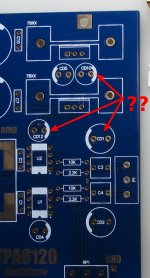
I bought this kit but it comes without schematic. I'm trying to figure out what capacitors are going on CD1, CD10, and CD12. The kit comes with two 50v,47uF; two 35v,220uF; and two 25v,100uF for those positions but I don't know which one goes where.
Would you be so kind and let me know where did you put them? I'm attaching a picture.
My second questions regards to your modification number "5)", I'm planning to change the 50Kohm pot for one of 10Kohm. My question: Is still recommended change the pot if I skip the modification number "3)" -which is a bit complicated for me- but I do indeed all others modifications?
Thank you very much.
Attachments
Last edited:
Hi Ferrosan,
My apologies for not replying your post sooner having not realized there were questions headed my way...
I hope you have figured out the locations of the caps without troubles, but this is what I would put them: CD1 is the same as CD2, they are the input coupling caps, 220uF in my kit, but 100uf will work just as well. CD12 is the same type as CD4 for NE5534 supply rails, CD10 same as CD5 at the supply regulators' output, 47/100/220 really don't make a difference.
As of the volume pot replacement, it's not NEEDED regardless performing the mod-3 or not, unless you experience DC offset problem or wiper noise issue. If the supplied pot is of 50K B type taper, or linear taper, it actually gets modified by the input resistance of the op-amp circuit (about 10K ohm) into somewhat Log type taper, or audio taper, which is what one would desire to have.....I'm about to revert mod-5 by swapping out the 10K pot and putting in a B-taper 25K or 50K pot. I found the 10K audio taper pot I currently have gives a bit too little action in the low volume range and a bit too much action in the high volume range than I'd like.
Hi Ferrosan,
My apologies for not replying your post sooner having not realized there were questions headed my way...
I hope you have figured out the locations of the caps without troubles, but this is what I would put them: CD1 is the same as CD2, they are the input coupling caps, 220uF in my kit, but 100uf will work just as well. CD12 is the same type as CD4 for NE5534 supply rails, CD10 same as CD5 at the supply regulators' output, 47/100/220 really don't make a difference.
As of the volume pot replacement, it's not NEEDED regardless performing the mod-3 or not, unless you experience DC offset problem or wiper noise issue. If the supplied pot is of 50K B type taper, or linear taper, it actually gets modified by the input resistance of the op-amp circuit (about 10K ohm) into somewhat Log type taper, or audio taper, which is what one would desire to have.....I'm about to revert mod-5 by swapping out the 10K pot and putting in a B-taper 25K or 50K pot. I found the 10K audio taper pot I currently have gives a bit too little action in the low volume range and a bit too much action in the high volume range than I'd like.
Thank you nattawa. Yes, finally I figured out where to put those caps observing some pictures where it’s for sell, it was more a "guess"
than any other thing, but your info helped me to confirm what I did was right.Currently the board is just half assembled so I can't comment but I will take in count your observation about the pot and I will try with a 25K too.
Thanks again.
50k-ohm B taper is a bit more suitable than a 25k pot if you are to keep the 10k resistor at ne5534 input unchanged, to maintain a 5:1 ratio for a better simulated log taper.
I have 6k8 in place of the 10k input resistor on my board, and that is why I was to try a 25kB pot , though there really is unlikely much of a difference. 50k pot seems to be a lot more easily sourced by the way.
I have 6k8 in place of the 10k input resistor on my board, and that is why I was to try a 25kB pot , though there really is unlikely much of a difference. 50k pot seems to be a lot more easily sourced by the way.
- Status
- This old topic is closed. If you want to reopen this topic, contact a moderator using the "Report Post" button.
- Home
- Amplifiers
- Headphone Systems
- schematic request for tpa6120/ne5534 ebay amp