Okay so I want to build a simple opamp based headphone amplifier.
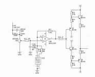
I came across a simple circuit (please see attachment) that utilizes an OPA2134PA. I checked my local electronics supplier and they have it in stock.
My first thought was to build it on breadboard, but then my friend said that he's going to make some PCBs for chipamps that he is building, and he said he could make me some PCBs while he is at it.
I made a design with ExpressPCB and was wondering if somebody here could check them out and say if these PCBs are good enough to use.
Also, can I opamp roll with this? I have a few different chips I'd like to try")
If this circuit is garbage, then please recommend me some better ones. Not anything too complicated or expensive, but something that has good sound and allows chip swapping.
Thanks!


I came across a simple circuit (please see attachment) that utilizes an OPA2134PA. I checked my local electronics supplier and they have it in stock.
My first thought was to build it on breadboard, but then my friend said that he's going to make some PCBs for chipamps that he is building, and he said he could make me some PCBs while he is at it.
I made a design with ExpressPCB and was wondering if somebody here could check them out and say if these PCBs are good enough to use.
Also, can I opamp roll with this? I have a few different chips I'd like to try
If this circuit is garbage, then please recommend me some better ones. Not anything too complicated or expensive, but something that has good sound and allows chip swapping.
Thanks!
Looks OK, worth a try. 2134 is exciting, until you get tired of the zing. Then try LM833.
Put storage caps on each rail, since Zo of batteries ain't too great.
How much gain do you have with your feedback resistors?
Edit1: you might need a current buffer stage depending on your listening level and the impedance of your cans. Most high performance amp designs do have an output buffer stage. But the opamp can source a reasonable amount of current, so try it first. It will distort if overdriven.
Edit2: 2134 has small DC offset so no problem, but some opamps have larger offset and will thump when you turn it on/off unless you use an output cap to stop the DC. Since the load is low impedance, you will need a large value cap to preserve low frequency response, which means dreaded electrolytic. :O Nichicon low leakeage is good for this.
Last edited:
Looks OK, worth a try. 2134 is exciting, until you get tired of the zing. Then try LM833.
What does zing mean?
Then try LM833.
I also like the 833, but it will have quite a bit more offset than the 2134.
What jcx said - but design the amp to drive a transformer primary, then wind the frafo's secondary to accommodate whatever headphone impedance you have.
Subjectively, the power supply matters the most in a headphone amp and a transformer gives a way to optimize the PSU whilst retaining the ability to drive a wide range of cans.
Subjectively, the power supply matters the most in a headphone amp and a transformer gives a way to optimize the PSU whilst retaining the ability to drive a wide range of cans.
A big thanks to all who replied!
My cans are AKG K142HD, 55 Ohms per side.
You can see more info here: AKG - K 142 HD
I have some LM833 that I salvaged from and old Philips theater in a box thingy, I might just try them. I currently also have some 45xx and 46xx op-amps (no 4562 sadly :/ ), JRC2904DX, and I think M5218A.
As for the power supply, I did put filter and decoupling caps on the board. Power supply will be a transformer and a regulator board. I will make the regulator board, and post it here
EDIT: Made this regulator board. Can be used with any 78xx and 79xx series regulators.
Last edited:
What do you guys think about this one?
portable headphone amp circuit | AFIATA.COM - Electronic Circuit Design
portable headphone amp circuit | AFIATA.COM - Electronic Circuit Design
You must like colored sound. Using 55 Ohm impedance give high THD if you use that schematic.
Colored sound with what, the first schematic? Well then recommend something better, I really don't know what to use.You must like colored sound. Using 55 Ohm impedance give high THD if you use that schematic.
How about a simple Cmoy with a socket to roll op-amps?
Someone give me an opinion on the second circuit please! Worth building and trying?
Thanks!
opamps like 5532 or so can only drive loads of 600 ohms or higher. but your headphone has only 50 ohm..........these opamps need a buffer amp (a current amplifier) at their output........ - example shown in the portable headphone circuit.
but i have not simulated or built that one.
but i have not simulated or built that one.
I don't think the second circuit will have much current with the small output devices used.
It will also have waaay too much gain at 22.4.
If you're looking for a good circuit to start with, why don't you try the "Lehmann" circuit below.
I've built several and they work quite well. PCB's and whole kits can be gotten from the Bay for less than $30.
It will also have waaay too much gain at 22.4.
If you're looking for a good circuit to start with, why don't you try the "Lehmann" circuit below.
I've built several and they work quite well. PCB's and whole kits can be gotten from the Bay for less than $30.
Attachments
I might try this one, thanks!I don't think the second circuit will have much current with the small output devices used.
It will also have waaay too much gain at 22.4.
If you're looking for a good circuit to start with, why don't you try the "Lehmann" circuit below.
I've built several and they work quite well. PCB's and whole kits can be gotten from the Bay for less than $30.
How is the sound quality?
And can this be used with single Op-amps, like dual mono?
If it's stable, that is. In simulation, I always had to restrict opamp bandwidth far more with a diamond buffer output (vs. a single EF) for a given level of stability. Maybe running the first buffer stage hotter would help.
This particular circuit has another problem - the value of R14 is silly, increasing impedance imbalance between the opamp input terminals even more. The datasheet recommends no more than 2k for good reason, here it can reach >20k. Besides, the 10k totally swamps the noise floor of the '2134. I'd recommend more like 470 ohms, and a 10k pot.
This particular circuit has another problem - the value of R14 is silly, increasing impedance imbalance between the opamp input terminals even more. The datasheet recommends no more than 2k for good reason, here it can reach >20k. Besides, the 10k totally swamps the noise floor of the '2134. I'd recommend more like 470 ohms, and a 10k pot.
Colored sound with what, the first schematic? Well then recommend something better, I really don't know what to use.
How about a simple Cmoy with a socket to roll op-amps?
Someone give me an opinion on the second circuit please! Worth building and trying?
Thanks!
You need a buffer after op-amp. Usually, op-amp can not directly drive low impedance load. The buffer can be inside the feedback or outside. Please search google or this site to find simple op-amp with buffer which can drive low impedance headphone.
Example: http://hifisonix.com/wordpress/wp-c...niversal-Small-Signal-Class-A-Buffer-V1.0.pdf
You can ask directly to Bonsai, a member of this forum who designed it.
It all depends heavily upon the type of opamp, the load and required levels though. I took some loaded measurements of my BTech BT928 back in the day, which is an inverting NE5532 based affair with 47 ohm output resistors, and distortion at elevated levels was measurable (about -80 dB of 2nd for a 100 ohm HD590, about -70 dB for a 32 ohm SHP805) but by no means unduly high or riddled with high-order harmonics.
Granted, I wouldn't use a TL072 for something like this, which is really wimpy. A '5532 (or NJM4580) is quite adequate already, especially when non-zero output impedance isn't disturbing. (Some headphone models are a lot pickier than others.) An NJM4556A will already get you pretty far, and two combined (like the O2 does) even further.
A discrete buffer is helpful for getting distortion down or enabling even more output current. It also allows using lower-noise opamps with less output current capability, and enables low output impedance. They tend to be run with significant amounts of standing current though, which usually precludes portable operation.
And no, there is no reason why you couldn't use single opamps.
Okay so I think I'll design a board for the Lehmann circuit, but with a single op-amp.
And use a smaller resistor on the input and a smaller pot.
The energy consumption is not an issue, since this will be a stationary amplifier. I use IEM's for portable sound, and they don't need any amplification
And use a smaller resistor on the input and a smaller pot.
The energy consumption is not an issue, since this will be a stationary amplifier. I use IEM's for portable sound, and they don't need any amplification
TBH I'd prefer a single-EF-buffer-in-feedback-loop circuit like the trusty Eaton. It needs some part value tweaks, like the pot and the gain that is way too high, and I'd drop the output AC coupling and series resistor (an RC zobel to power ground should be added in return), but the topology is promising. (The various enhancements of this circuit that you'll find posted on the web do most of that but tend to contain major misimprovements, like Darlingtons used for the buffer transistors. Those run at minimal bias current, and if you do try to increase it, they tend to blow up in no time.)
- Status
- This old topic is closed. If you want to reopen this topic, contact a moderator using the "Report Post" button.
- Home
- Amplifiers
- Headphone Systems
- OPA2134 headphone amplifier or recommend something better