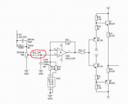
In the circuit posted below, can someone please explain why the designer used a 10K ohm resistor in series with the input?
I see that the 10K resistor and 100pF cap form a low pass filter.
I typically see resistors from 100-1K ohms used in this position.
Would the circuit benefit in any way from a smaller input series resistor and larger shunt cap? Say like a 2K resistor and 1000pF cap?
Thanks...
I see that the 10K resistor and 100pF cap form a low pass filter.
I typically see resistors from 100-1K ohms used in this position.
Would the circuit benefit in any way from a smaller input series resistor and larger shunt cap? Say like a 2K resistor and 1000pF cap?
Thanks...
Attachments
Less variation of low pass filter cut-off frequency.
So no advantage(s) of using a lower value resistor there?
So no advantage(s) of using a lower value resistor there?
Lower noise, although the 50K pot used at the input is much noisier.
You can put a 100pf across R22... to avoid possible oscillations at higher freqs, check with scope if needed or not.
You can also lower value of R22 and keep same ratio with R16 and R18. Lower resistor values here will result in lower thermal noise.
Need power supply 0.1uf bypass across the V+ (pin8) and V-(pin4) pins to Gnd.
You can also lower value of R22 and keep same ratio with R16 and R18. Lower resistor values here will result in lower thermal noise.
Need power supply 0.1uf bypass across the V+ (pin8) and V-(pin4) pins to Gnd.
You can put a 100pf across R22... to avoid possible oscillations at higher freqs, check with scope if needed or not.
You can also lower value of R22 and keep same ratio with R16 and R18. Lower resistor values here will result in lower thermal noise.
I don't own a scope, so I can't check for oscillations.
I've been using 2K for R22 instead of 4.7K.
Thanks for the tips...
- Status
- This old topic is closed. If you want to reopen this topic, contact a moderator using the "Report Post" button.
- Home
- Amplifiers
- Headphone Systems
- Why such a large input series resistor?