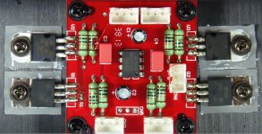
I found a photo of a commercial design, that uses a OPA2134 along with a pair of IRF510's for the output, that I would like to build and try.
As seen in the photo, there's also a pair of LM317T regulators which I assume are used as some type of CCS for the 510's.
All the through-hole resistors appear to be the same value.
C3 & C4 appear to be Wima caps. perhaps used as coupling caps. on the inputs?
Can someone, who understands this circuit, please draw up and post a schematic of it?
Thanks...
Attachments
I don't know anything about this circuit, but I don't see how it could be an effective headphone amp. I'd guess it's part of a larger system, maybe it's some sort of voltage or current regulator (can be accomplished with an op amp & 317s)? Just shooting in the dark here. Do you have any other pics?
the 1st question for headphone amp projects should always be "for which headphone?"
they vary by orders of magnitude in Z, sensitivity, required I,V
MOSFET buffers can waste a lot of Vsupply - whether that matters depends on what the particular model of headphones you want to drive need
lots of various project amps have been posted over the years
DIY Projects | HeadWize
Designing An Opamp Headphone Amplifier | HeadWize
I don't know anything about this circuit, but I don't see how it could be an effective headphone amp. I'd guess it's part of a larger system, maybe it's some sort of voltage or current regulator (can be accomplished with an op amp & 317s)? Just shooting in the dark here. Do you have any other pics?
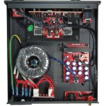
Here's a photo of the interior:
Attachments
Should be similar to what's been discussed in this thread, opamp + Class A MOSFET follower w/ LM317 CCS, either inside or outside the feedback loop. Pretty standard stuff in DIY about a decade ago. Not especially efficient, obviously (a push-pull output could deliver twice the current, not to mention the possibility of transitioning into AB), but simple, easy to bias and doing well in terms of distortion.
Here's how a basic Szekeres (just the buffer) will fare with and without a CCS.
Instead of the MOSFET, it basically is also possible to use a BJT, a Darlington - or even another LM317 (there's a thread on that somewhere in this forum).
Here's how a basic Szekeres (just the buffer) will fare with and without a CCS.
Instead of the MOSFET, it basically is also possible to use a BJT, a Darlington - or even another LM317 (there's a thread on that somewhere in this forum).
Should be similar to what's been discussed in this thread, opamp + Class A MOSFET follower w/ LM317 CCS, either inside or outside the feedback loop. Pretty standard stuff in DIY about a decade ago. Not especially efficient, obviously (a push-pull output could deliver twice the current, not to mention the possibility of transitioning into AB), but simple, easy to bias and doing well in terms of distortion.
Here's how a basic Szekeres (just the buffer) will fare with and without a CCS.
Instead of the MOSFET, it basically is also possible to use a BJT, a Darlington - or even another LM317 (there's a thread on that somewhere in this forum).
So, are saying I'm better off building a Lehmann design, which uses BD139 and BD140 output devices, instead of using MOSFET's?
If not, can you point me to some designs that you consider to be very good?
I'm not really interested in building designs that are considered "out of date".
you still haven't said which model headphone - need the Impedance and Sensitivity numbers to even pick a power supply V
and "universal" isn't an option in headphone amps with orders of magnitude sensitivity range
some headphones and some amps won't work together well - high sensitivity headphones will hiss and be using a tiny, often poorly matched high attenuation setting on the volume pot with the "wrong" amp
and "universal" isn't an option in headphone amps with orders of magnitude sensitivity range
some headphones and some amps won't work together well - high sensitivity headphones will hiss and be using a tiny, often poorly matched high attenuation setting on the volume pot with the "wrong" amp
you still haven't said which model headphone - need the Impedance and Sensitivity numbers to even pick a power supply V
SENNHEISER HD 580
the HD580 is speced as 300 Ohms and 97 dB/mW so 11 Vpk, 36 mApk would drive them to 120 dB SPL - that's fairly loud, really only "needed" for reproducing live event listening level transient peaks
some op amps can do that without buffering, even more if you parallel the outputs "A47" style
if you want well documented projects there are lots of options, some even with kit suppliers
the O2 project claims to be good enough with cheap parts
I like DSL driver CFA op amps instead of unity gain buffers, they certainly outperform any less than a dozen parts discrete buffers I've seen anywhere within the op amp's I,V limits
even if you want Class A I believe a few DSL driver op amps have enough internal output stage bias to drive HD580 to over 100 dB SPL before leaving Class A - and still control the distortion to below audible, i.e. distortion alone below human hearing threshold in quiet after leaving Class A
and they have enough extra current output capability that even ccs pull down is practical up to full Class A for HD590
I use the TPA6120 largely for the excellent datasheet audio specs - no guessing required
other DSL or CFA may do really well too, I expect most beat commonly used unity gain buffer chips which never show the raw chip' distortion numbers - only the composite amp
Scott Wurcer snuck in a audio frequency THD plot on the AD815 DS
getting the heat out is an issue if you need to operate at higher power, hand soldering the various power pad arrangements probably have slowed hobbyist use
but for HD595 you really don't need to solder down the power pad - the TPA6120 chip is fine dissipating over a watt without soldering to the bottom pad
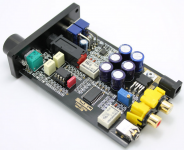
Yeah, the biggest problem I see with using the TPA6120 or the AD815 is a PCB.
I'm not into making my own PCB's. I'm not experienced enough to design boards nor do I have the money to have only a few boards manufactured.
My understanding is board layout, ground planes, etc. are really critical when working with these high-speed IC's.
Would one of these units off Ebay, pictured below, be a good choice to begin with? Looks as though I can install whichever op-amp I want.
Attachments
not saying you can - I don't keep up with kits or cheap mass market offerings
but generally in consumer electronics anything someone tools up to build in the thousands will be sold retail for less than a hobbyist can even buy the raw parts for in singles
at ~$50-60 that amp looks like its offering great value - even if I would like to see some differences in layout, would need schematic and parts list, PCB to guess more
Last edited:
active "supply splitter" makes a buffered 1/2 way point between the supply V, call it ground and you're good
as long as the input power is isolated, floats to accommodate anything you plug into on the signal gnd side
unfortunately the idea, while it can be implemented with acceptable quality, costs power
and some on Headwize got bored and invented the technically flawed "3-channel" idea that separates the signal gnd from the buffered "output gnd" - adding the buffer's noise, distortion, crosstalk to the output
but they insist "it soundz good" despite it objectively failing several of their own claims of what technical aspects they think it improves - the O2 site has measurements verifying the circuit theory analysis of "3-channel gnd" failings
Last edited:
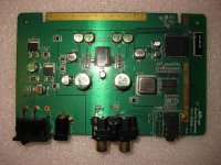
I have an old bluetooth audio receiver meant for Apple products that uses a 6120 for the outputs and runs off a single supply.
I bought it to try and use with non-apple devices but it had a weird "blip" in the sound every few seconds so I never really used it. I've thought about converting it to a headphone amp.
I bought it to try and use with non-apple devices but it had a weird "blip" in the sound every few seconds so I never really used it. I've thought about converting it to a headphone amp.
Attachments
- Status
- This old topic is closed. If you want to reopen this topic, contact a moderator using the "Report Post" button.
- Home
- Amplifiers
- Headphone Systems
- OPA2134/IRF510 Schematic...