I got a smoking deal on nearly 2000 ne5532. So im going for ridiculously low output impedance. I dont think heat will be an issue but ill keep an eye on it and make adjustments if necessary.
I will try both SE and BAL. BAL for power amp for sure. I'll try adjustable supplies starting with 15v rails and increase.
JCX I read more in the book and know what you are talking about. Power input to each module will have a small sea of caps for the return on SE.
I'm just working on board design right now so looking forward to your results Charlie.
Oh, additionally the ne5532 modules will be working as a buffer. The gain circuit will be on a separate board so I can try different front ends.
Let me say it again: how are you going to remove all the heat generated by each SMD 5532? The problem with the power amp is that the output is limited by the rail voltage. The 5532 is no rail-to-rail so there is probably about 3V below the rail voltage that can be reached by 5532 output. Let's say you are running the rails at +/-15Vdc. The 5532 can only produce output to +/-12Vdc. This is the PEAK voltage, so RMS is 0.707 times that, or 8.48V. Power is Vrms^2/R. If R is 8 ohms, the max power you can deliver to the load is 9W (single ended), double that if using a 4 ohm load. It doesn't matter how many thousands of 5532s you have in parallel, the limits on the rail voltage means you can't deliver more power into the load, you are only disributing that power over more devices as you multiply the number of 5532s used. You can use lower impedance loads, but you only gain in a linear fashion. Increasing the voltage gets a square law increase, but you can't really do that more than another volt or two.
I based my example above on +/-15Vdc rails. I have seen Self mention that some versions of the 5532 are rated up to 22V rails but even he runs his Op-Amplifier at 18.3 regulated rails and the rated output is about 16W@8ohms. He's using the DIP package, which is larger and has somewhat larger area for heat dissipation. But Self mentions that the package gets "pretty warm" when run at this voltage. I think he would like to use higher voltage rails, but I think he knows that any higher will be thermally dangerous. I think you will not be able to use rails that are quite as hot because you are using the SMD package.
But if you are only looking for a few Watts of power (for example to power a 110dB/W compression driver) then the 5532 based amplifier is useful and has low distortion. For general amplifier duties, it's more of a curiosity. There are some very nice, low distortion, solid state designs out there that are a better bet when you need power above about 10W. I'm not trying to dissuade you from building your 5532 monster, just making sure these issues are out in the open.
On the other hand, a headphone amplifier rarely has to deliver over a few volts of output, and impedances are higher (usually at least 32 ohms up to a couple of hundred ohms), so the 5532 based amplifier is perfect for that application.
Last edited:
Having a huge amout of opamps I have no dissipation problems.
No, the number of op-amps is not the problem. Adding more is not going to reduce the per-package dissipation. The package can only dissipate so much power - it's a heat transfer problem. The dissipation I am talking about has nothing to do with the signal in or out, it's the quiescent dissipation of the device just sitting there, connected to the rails but otherwise doing nothing. This is what is really going to limit the rail voltage that you can use.
Here is some data from the Onsemi 5532 datasheet:
What does this tell us? #1 the DIP and SOIC-16 package have the same max power dissipation at 25C but the SOIC-8 package is rated about 35% less. #2 the DIP package can lose its heat fastest (has the lowest thermal resistance), followed closely by the SOIC-16 package, while the SOIC-8 package has 25% more thermal resistance, meaning it is 25% worse at transferring its heat out to the air.Maximum Power Dissipation, Tamb = 25°C (Still-Air)
SOIC-8 Package: 780mWThermal Resistance, Junction−to−Ambient
DIP Package: 1200mW
SOIC-16 Package: 1200mW
SOIC-8 Package: 182 °C/W
DIP Package: 130 °C/W
SOIC-16 Package: 140 °C/W
The quiescent current for each device is 8-10mA. Let's be conservative and choose the 10mA figure. At +/-15V this translates to 300mW of power dissipated in the package, which will cause it to heat up:
The SOIC-8 Package @ 182 °C/W heats up 55C to 80C (176F).
The DIP Package @ 130 °C/W heats up 39C to 64C (147F).
The SOIC-16 Package @ 140 °C/W heats up 42C to 67C (153F).
Increasing the voltage to +/-20V and you get 400mW of power dissipation:The DIP Package @ 130 °C/W heats up 39C to 64C (147F).
The SOIC-16 Package @ 140 °C/W heats up 42C to 67C (153F).
The SOIC-8 Package @ 182 °C/W heats up 73C to 98C (208F).
The DIP Package @ 130 °C/W heats up 52C to 77C (170F).
The SOIC-16 Package @ 140 °C/W heats up 56C to 81C (178F).
What does this all mean? Note that the 5532 (from the datasheet) is only rated for operation up to 70C. So in reality none of the packages will be operating within their rated limits when powered by +/-20V rails and sitting in still 25C (or more) air inside a case. The SOIC-8 package exceeds 70C even with +/-15V rails, so I hope that you have the SOIC-16 version... This likely explains why Mr D. Self set his rail voltages at 18Vdc.. it's exactly the voltage where the dissipated power pushes up the DIP package temperature to 70C, the maximum for safe and reliable operation. The DIP Package @ 130 °C/W heats up 52C to 77C (170F).
The SOIC-16 Package @ 140 °C/W heats up 56C to 81C (178F).
If you exceed 70C the board may initially work but after some time some devices may fail. How will you find the failed 5532s if the packages are all soldered down? Self mentions this very point in the Elektor article on his op-amplifier and includes removable jumpers that can be used to help track down a problematic device on the board (and that was for the DIP package version).
Don't let me totally dissuade you. Give it a try and post about what happens. But try to keep the above points in mind during your design and testing!
SOIC-8
Good info Charlie! I found the thermal resistance to change per manufacturer. TI is much lower than the rest. Disturbingly so. I guess I could use thermal adhesive and foil. I've no problem with a fan. Looks like I'll need one.
I do have an easy way to find which opamp is shot but I wonder if I'll ever know one died.
SOIC-8
Good info Charlie! I found the thermal resistance to change per manufacturer. TI is much lower than the rest. Disturbingly so. I guess I could use thermal adhesive and foil. I've no problem with a fan. Looks like I'll need one.
Yeah I noticed that too, about the dissipation data on the TI datasheet. Very odd...
That thermal paste+foil is not a bad idea at all. In fact you might be able to design the board so that you could contact some metal with the top of all the SOICs (plus some thermal grease on each SOIC), and that metal could be a heatsink, or connected to one. This would transfer a lot more heat than simple contact with air! In that case you could probably hike up the voltage to 20V rails. I think the limiting factor for the SOIC packages is purely due to the much smaller overall surface area compared to the dip package.
I do have an easy way to find which opamp is shot but I wonder if I'll ever know one died.
That all depends on how the op-amp "fails". Maybe it fails by connecting one of the rails to the output! In that case you would definitely know...
Last edited:
Hi Charlie,have you performed any measurements yet?
By the way,any chance to check the final version of your schematics?
Thanks
I haven't built it yet, in fact I still don't have the circuit boards. I'm waiting for the fab to ship them to me...
The circuit is pretty straightforward: unity gain input buffer driving many paralleled unity gain 5532 buffers.
I'll post more info once I build and test the first board.
UPDATE:
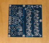
I finally got the circuit boards after a bit of a delay. I might try to build one up but I have a couple of other boards that I need to build first. In the attached rather grainy photo the PS is on the left and the op-amps on the right. Half are on the top and the other half are on the bottom out of view.
I finally got the circuit boards after a bit of a delay. I might try to build one up but I have a couple of other boards that I need to build first. In the attached rather grainy photo the PS is on the left and the op-amps on the right. Half are on the top and the other half are on the bottom out of view.
Attachments

I finally can come back to this project. I had to put it on the back burner while I worked on some other stuff, and then I packed up and moved my house contents... this explains the month long delay.
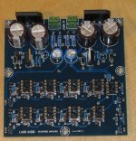
The pic below shows the board near completion. I've finished populating it, but have realized that I made an error with the polarity of capacitor C24 (upper right in pic). It's reversed, but it's just a simple matter to solder it in the "other" way, and I can edit the silkscreen to properly show the correct polarity (for the other boards that I had made) so this is really a minor issue at best.
I will replace the cap and install the new one with the polarity corrected. At that point after a little checkout I can test the board and will report the results here.
Attachments
Finally, some test results to post!
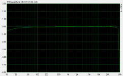
I populated the board with the LME49720 input buffer and four NE5532 op-amps (the Texas Instruments version). I put all of the 5532 buffers on one channel and left the other channel vacant, and tested in this configuration.
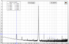
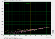
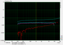
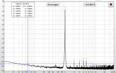
Attached are the measured frequency response, distortion, and a spectrum with a 1kHz input. I measured the output at 1.06Vrms during the spectrum measurement.
I'd say that this looks pretty good for a headphone amp. The frequency response (on the low end especially) is even flatter than this measurement would indicate as the amp is DC coupled. The harmonic distortion is at or below 0.001% for all orders and power supply related components are very low. Mains frequency is almost at -120dB! I still can't figure out what that spike is at 20kHz it's something that has popped up in my measurements only since my move.
Only half of the output buffers populated for these tests. One nice aspect of this design is that you don't have to fully build it out unless you want the ability to drive very low impedance headphones (e.g. 32 ohms) or possibly multiple cans in parallel.
I populated the board with the LME49720 input buffer and four NE5532 op-amps (the Texas Instruments version). I put all of the 5532 buffers on one channel and left the other channel vacant, and tested in this configuration.
Attached are the measured frequency response, distortion, and a spectrum with a 1kHz input. I measured the output at 1.06Vrms during the spectrum measurement.
I'd say that this looks pretty good for a headphone amp. The frequency response (on the low end especially) is even flatter than this measurement would indicate as the amp is DC coupled. The harmonic distortion is at or below 0.001% for all orders and power supply related components are very low. Mains frequency is almost at -120dB! I still can't figure out what that spike is at 20kHz it's something that has popped up in my measurements only since my move.
Only half of the output buffers populated for these tests. One nice aspect of this design is that you don't have to fully build it out unless you want the ability to drive very low impedance headphones (e.g. 32 ohms) or possibly multiple cans in parallel.
Attachments
Since these were just "first look" measurements I have only used the soundcard input as a load (e.g. 10k ohm) to get a general idea of distortion and PS rejection, etc. The load will really only effect the performance from the 5532s, and their behavior with various loads is pretty well documented by Doug Self. I don't expect too see any significant differences as long as you stay within the design specs.
I have not tested it into loads characteristic of headphones yet, but I will try to do that later today with a fully populated channel.
I have not tested it into loads characteristic of headphones yet, but I will try to do that later today with a fully populated channel.
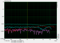
I decided to throw on a load and see what happens. I cobbled together a 30R load from some 10 Watt wire would resistors and retested.
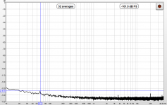
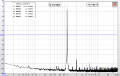
The results are about the same, if not better, compared to the no-load measurements. See attached. Distortion is still 0.001% or less. The surprising result is that the power supply mains and harmonics have more or less disappeared from the spectrum and even with no input signal the spectrum looks very clean.
In retrospect, the output voltage is only 1V. Only the load seen by the output buffers has changed and the 5532 is known to perform very well into very low loads. When you add in the fact that the output only needs to reach 1Vrms, you can easily see that this is well within the capabilities of the board, populated with 4-op-amps (per channel) out of the maximum 8.
Unlike the previous no-load conditions, I can feel the regulators getting slightly warm. The 5532s run barely warm under the +/-15V rails into this load. It will be interesting to see what happens when the board is fully populated as the quiescent current of the 5532s is not insignificant.
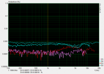
Attached are screen shots from the measurements taken with a 30.3 ohm load connected, one channel only, populated with four 5532 packages:
The results are about the same, if not better, compared to the no-load measurements. See attached. Distortion is still 0.001% or less. The surprising result is that the power supply mains and harmonics have more or less disappeared from the spectrum and even with no input signal the spectrum looks very clean.
In retrospect, the output voltage is only 1V. Only the load seen by the output buffers has changed and the 5532 is known to perform very well into very low loads. When you add in the fact that the output only needs to reach 1Vrms, you can easily see that this is well within the capabilities of the board, populated with 4-op-amps (per channel) out of the maximum 8.
Unlike the previous no-load conditions, I can feel the regulators getting slightly warm. The 5532s run barely warm under the +/-15V rails into this load. It will be interesting to see what happens when the board is fully populated as the quiescent current of the 5532s is not insignificant.
Attached are screen shots from the measurements taken with a 30.3 ohm load connected, one channel only, populated with four 5532 packages:
Attachments
-
 LA-A1 with 4 op-amps per ch into 30R no signal spectrum.PNG58.5 KB · Views: 179
 -
 LA-A1 with 4 op-amps per ch into 30R spectrum.PNG74.3 KB · Views: 193
 -
 LA-A1 with 4 op-amps per ch into 30R STEPS distortion.PNG42.2 KB · Views: 551
 -
 LA-A1 with 4 op-amps per ch into 30R ARTA FR dist.PNG38.6 KB · Views: 564
Last edited:
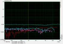
To compare, attached is the distortion measurement taken when the board is populated with only one 5532 op-amp per channel. You can see it is rising with frequency and is about 5 times higher at 1kHz and higher order products are increasing as well. Not that you would likely notice. The distortion is still quite low. It's pretty amazing that the 5532 is still this good when this heavily loaded (70R per amplifier)!
Attachments
Now measurements with the maximum eight 5532 op-amps installed (still only one channel populated). The distortion levels actually decreased a bit compared to when 4 op-amps were used. The spectrum still looks very clean. The loading on each amplifier (16 total per channel) is about 490R. The drive level is again producing about 1Vrms at the output and the load is 30.3R.
The regulators are now pretty warm to the touch, but I can just keep my finger on them. I should definitely add a small heatsink if/when both channels are fully populated with output buffers. The TO-220 tabs could just be connected to an extruded alu case and that would be enough. The 5532s are not warm - I think I was mistaken before. The rail voltages are actually only about +/-14V and this helps to keep them running cool.
The regulators are now pretty warm to the touch, but I can just keep my finger on them. I should definitely add a small heatsink if/when both channels are fully populated with output buffers. The TO-220 tabs could just be connected to an extruded alu case and that would be enough. The 5532s are not warm - I think I was mistaken before. The rail voltages are actually only about +/-14V and this helps to keep them running cool.
Attachments
Last edited:
My headphone amp project is working very well, so... what else can we do with it?
I'm now thinking about trying to power a loudspeaker driver with it. Pro sound drivers can be had with 16 ohm nominal impedance and are high efficiency. A pro compression driver might be a perfect candidate for instance. You would only need a few Watts for normal home use.
Two of these boards could be used in parallel with a suitable buffer driver. If all four of the channels (from two boards) were paralleled, you could even drive 8 ohms loads. With /-15V rails you are probably looking a maximum power output of Vrms^2/R = [0.707*(15v-3v)]^2/8 = 9 Watts into 8R, half that into 16R, and distortion would rise as this power output was approached. But if the compression driver is 105-115dB/W efficient, this is plenty of power.
Thanks for humoring me Charlie. Definitely glad I asked.
Have you made any progress on your own 5532 project? One thing that popped into my head yesterday was that if you have many, many more 5532s in parallel you will need something to drive them, e.g. supply current to the input pins. IIRC the input impedance can be as low as 30k, and for instance that would mean that eight in parallel is a load of 3750 ohms (my amp). In a massively parallel circuit it's almost like you need a 5532 to drive every group of N 5532 output buffers!
- Home
- Amplifiers
- Headphone Systems
- My LM5532 Headphone Amplifier project