I purchased a gross of 5532 op amps back when I was interested in building Douglas Self's 5532 Op-Amplifier (Elektor) project. I never got around to building it, but I now find myself wanting to build a headphone amplifier. Adapting some aspects of Self's amp to my headphone amplifier project seems like a great use of my existing op-amp stash.
This amp is probably slightly different than some others out there. I will be driving the input from a preamp that has some good voltage gain so the headphone amplifier can be unity gain input to output. The design is basically a buffer, a bunch of (16) amplifiers in parallel with current sharing resistors, and a DC servo. The input buffer 5532 alone can have some DC offset - up to about 50mV for the values I am using. I happen to have a bunch of OP-07s around that I can use for the servo, so I threw it in there just in case eliminating the offset is actually useful.")
I borrowed the unbalanced input from Self's 5532 amplifier and some of his other published work and tweaked a value or two as needed. The buffer is mainly to allow for AC coupling and to provide drive for all 16 parallel inputs.
When dimensioning the current stage I assumed a load of 32R, which I guess is the low end for what you can expect from headphones. This load would result in each op amp seeing just over 500 ohms, which should keep distortion low and the op-amps happy. I didn't bother to include an output zobel.
I will power all 5532s from a well-heatsinked +/-15V 317/337 regulated power supply.
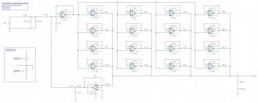
Below is the schematic for one channel. The other is identical. Comments welcome, especially if I have overlooked something.
This amp is probably slightly different than some others out there. I will be driving the input from a preamp that has some good voltage gain so the headphone amplifier can be unity gain input to output. The design is basically a buffer, a bunch of (16) amplifiers in parallel with current sharing resistors, and a DC servo. The input buffer 5532 alone can have some DC offset - up to about 50mV for the values I am using. I happen to have a bunch of OP-07s around that I can use for the servo, so I threw it in there just in case eliminating the offset is actually useful.
I borrowed the unbalanced input from Self's 5532 amplifier and some of his other published work and tweaked a value or two as needed. The buffer is mainly to allow for AC coupling and to provide drive for all 16 parallel inputs.
When dimensioning the current stage I assumed a load of 32R, which I guess is the low end for what you can expect from headphones. This load would result in each op amp seeing just over 500 ohms, which should keep distortion low and the op-amps happy. I didn't bother to include an output zobel.
I will power all 5532s from a well-heatsinked +/-15V 317/337 regulated power supply.
Below is the schematic for one channel. The other is identical. Comments welcome, especially if I have overlooked something.
Attachments
.
Interesting project. One gasps.
Your 10 ohm output/loading/matching resistors are 51 ohms in "Burr-Brown Corporation AB-051" (google including quotes).
A possible value of 5 ohms is listed in "Intersil AN1111.1" (google again).
Apparently there's some flexibility.
Just to to toss in 2 cents.
The data sheet says the NE5532 can drive 600 ohms (per amp). This suggest to me that:
2 drive 300 ohms.
4 drive 150 ohms.
8 drive 75 ohms.
16 drive 37 ohms, call it 32, which is pretty much as low as headphones go. It seems you've covered every headphone known to man.
.
Last edited:
.
Thinking about it, I wonder if bias current might not be a problem.
Worst-case bias current is 1ma in the data sheet. This would require the buffer to supply 16ma, which is pushing things about to the limit. Although certainly worst case times 16 is unlikely, just a thought.
.
Thinking about it, I wonder if bias current might not be a problem.
Worst-case bias current is 1ma in the data sheet. This would require the buffer to supply 16ma, which is pushing things about to the limit. Although certainly worst case times 16 is unlikely, just a thought.
.
Have a look at this. With just a minor extra complexity you can achieve somewhat more interesting result What "dead bug" can do? : diyaudio
.
Worst-case bias current is 1ma in the data sheet.
I see worst case input bias current (Ib) as 1uA on T.I data sheet ?
I suspect you may need the k versions of the regulators. Depending on the input voltage, the dissipation may be too much to handle for the plastic ones. The 5532 is not gentle in idle consumption. Just 3 of them in my active crossover are enough to make TO220 regulators run toasty. I unfortunately have a very high input voltage, but still. Better to be safe.
Edit, 600 ohm performance of the 5532 is extremely poor. Opamp loading distortion was tested - author's name escapes me - and distortion at low loads of most common opamos was found to be terrible. I think the paper recommended a load of no less than 5k per opamp.
Edit, 600 ohm performance of the 5532 is extremely poor. Opamp loading distortion was tested - author's name escapes me - and distortion at low loads of most common opamos was found to be terrible. I think the paper recommended a load of no less than 5k per opamp.
Last edited:
Edit, 600 ohm performance of the 5532 is extremely poor. Opamp loading distortion was tested - author's name escapes me - and distortion at low loads of most common opamos was found to be terrible.
Samuel Groner's epic op amp distortion paper has it on page 352(!) of the pdf link under "op amp distortion" here:
SG-Acoustics · Samuel Groner · IC OpAmps
The THD+N graph of the NE5534 at 10KHz with a 600R load and +/-15Vdc rails (30V) vs. output amplitude is around 0.05% at the best. Extrapolating the plot in my head I would take a guess of somewhere around 0.1% at 20KHz.
Last edited:
Samuel Groner's epic op amp distortion paper has it on page 352(!) of the pdf link under "op amp distortion" here:
SG-Acoustics · Samuel Groner · IC OpAmps
The THD+N graph of the NE5534 at 10KHz with a 600R load and +/-15Vdc rails (30V) vs. output amplitude is around 0.05% at the best. Extrapolating the plot in my head I would take a guess of somewhere around 0.1% at 20KHz.
The actual plot shows no better than 0.2% at any frequency or output voltage into a 600 ohm load. At the test impedance of 2.2k ohms, distortion drips to below 0.01% as the output approaches 0dBu. That's twenty times as much distortion.
Caveat, I only have a very old copy, mine has the 5532 results on page 172 or something.
The actual op amp used in the project is the 5532. I used the 5534 model because that was as close as I could come in my SPICE package to 5532. The are essentially the same, except the 5534 is a single amplifier package with external compensation while the 5532 is dual with internal compensation.
@ sangram: Anyone telling you that a 5532 produces terrible distortion (like 0.2%) at 500R or 600R load should throw away their ICs and get genuine ones. Douglas Self has studied these ICs ad nauseum and they are used in lots and lots of professional studio gear, mixing consoles, etc. They are very low distortion and low noise. Here is a plot of the distortion of the 5532 used as a voltage follower buffer as a function of the input resistance to the buffer from the previous stage:
Image Source: Op amps in small-signal audio design - Part 2: Distortion in bipolar and JFET input op-amps | EE Times
I did a little more investigation of the input bias current issue - this is definitely causing about 50mV offset (exact magnitude depends on resistor value to ground on input buffer's non inverting input). If change the input buffer op amp to the LME49720 I get almost zero offset and I can then eliminate the DC servo.
Remember, this project is to use up my stock of 5532s so that is what I am going to employ here to supply output current.
@ sangram: Anyone telling you that a 5532 produces terrible distortion (like 0.2%) at 500R or 600R load should throw away their ICs and get genuine ones. Douglas Self has studied these ICs ad nauseum and they are used in lots and lots of professional studio gear, mixing consoles, etc. They are very low distortion and low noise. Here is a plot of the distortion of the 5532 used as a voltage follower buffer as a function of the input resistance to the buffer from the previous stage:
An externally hosted image should be here but it was not working when we last tested it.
Image Source: Op amps in small-signal audio design - Part 2: Distortion in bipolar and JFET input op-amps | EE Times
I did a little more investigation of the input bias current issue - this is definitely causing about 50mV offset (exact magnitude depends on resistor value to ground on input buffer's non inverting input). If change the input buffer op amp to the LME49720 I get almost zero offset and I can then eliminate the DC servo.
Remember, this project is to use up my stock of 5532s so that is what I am going to employ here to supply output current.
There is some nice info on the 5532 from Douglas Self from his old site at this link:
The 5532 Opamp
The 5532 Opamp
Charlie, do look at the paper referenced, we're talking about 600 ohm loading distortion, hardly something you encounter inside a console. I use them a lot, and one thing I would not use them for is driving low load impedances.
The Samuel groner paper clearly illustrates the effect of moving from a 2k2 load to 600ohm load. Your graph shows the distortion plot as a function of source impedance of the previous stage. Not the same thing.
The Samuel groner paper clearly illustrates the effect of moving from a 2k2 load to 600ohm load. Your graph shows the distortion plot as a function of source impedance of the previous stage. Not the same thing.
Do note that Samuel Groner's measurements were carried out at a noise gain of 60 dB. At unity gain the opamp will have far more GBW to work with, and accordingly distortion will be far lower. (Douglas Self showed that two 5532 sections in parallel can drive 5V into 220 ohms well, and 4 the same into 100 ohms, so at 16 you should be good down to 25 ohms at least.) In fact, I would not be surprised to see common-mode distortion dominate at high frequencies, depending on which manufacturer's 5532 we are talking about.
I would be slightly worried about stability in this design. A Zobel network at the output may be useful to avoid oscillation with high impedance capacitive loads. A headphone cable alone may have 1 nF or more. If you can, test the finished amplifier with 10 nF and 47 nF.
Instead of the DC servo, you could also use a plain RC in the feedback loop of the first stage. 47k||100µ bipolar or so. Expected DC offset would be no bigger than about 10 mV even without anything.
BTW - R2, R3 look a bit small. Usually I would expect these to be in the 10s or even 100s of kOhms.
EDIT: 50 mV of offset would indicate that input bias current in these 5532s is around 1000 nA, far in excess of the usually spec'd 200 nA. Whose manufacturer's parts are we talking about? It's not the first time I hear about something like this.
Last edited:
Do note that Samuel Groner's measurements were carried out at a noise gain of 60 dB.
Aha, that's it.
I was staring at that awhile last night after the post. The Groner numbers were two orders of magnitude off from Self and from some of the part datasheets. Something wasn't apples-to-apples.I'm not sure why someone would try to use the 5532 at high gain. It's not good in that role. Even Self in his 5532 Op-Amplifier employs a multiple stage input section, some stages with two op-amps in parallel to reduce noise a little, to not require more than about 10dB gain per stage. Also, its best with low impedance networks connected to it. Don't use it like a JFET input amp.
When used at low gains or as a voltage follower the 5532's noise and distortion performance is very good. It's quite inexpensive and can drive 600 ohm loads easily. As long as you use it wisely you will not be disappointed.
When used at low gains or as a voltage follower the 5532's noise and distortion performance is very good. It's quite inexpensive and can drive 600 ohm loads easily. As long as you use it wisely you will not be disappointed.
I would be slightly worried about stability in this design. A Zobel network at the output may be useful to avoid oscillation with high impedance capacitive loads. A headphone cable alone may have 1 nF or more. If you can, test the finished amplifier with 10 nF and 47 nF.
Thanks for the advice about the Zobel. Here is my question: if each 5532 in the output stage has its own 10R series resistor, why would a Zobel be needed? The typical one is a 10R in parallel with an inductor that cuts in at higher frequencies. So the result is a 10R impedance at higher frequencies (above audio band) and approaching zero impedance at low frequencies within the audio band. Why not just use a 10R and be done with it? Since there are 16 op-amps, the output impedance for the lot in parallel is 10/16, or less than 1 ohm. Does this sound OK?
Instead of the DC servo, you could...
I changed the input buffer op-amp type to an LME79720 and then balanced input impedances. The resulting offset is so low I don't need a servo (at least not in the sim!). DC on the input is blocked by the cap.
EDIT: 50 mV of offset would indicate that input bias current in these 5532s is around 1000 nA, far in excess of the usually spec'd 200 nA. Whose manufacturer's parts are we talking about? It's not the first time I hear about something like this.
According to Self, the bias current of the 5532 (Fairchild) is about 200nA nominal, 800nA max. If you have a 100k resistor from non-inverting input to ground, the bias current will result in 20mA to 80mA at the output. To that you have to add the input offset voltage of 4mV. My sims bear out these numbers. That's why I changed to a different type for the input with a much smaller bias current and therefore inherently smaller output offset that doesn't need correcting.
Speaking of apples to apples, the results for input impedance distortion would seem to agree beautifully. Douglas Self (graph above) gets 0.0035% at 10 Vrms, 10 kHz, 10 kOhms, while Samuel Groner with 10 times the source impedance at a slightly lower level of 7.75 Vrms gets about 0.03% (expected value from the above: about 0.027% - close enough).
Well, here it was done to get distortion high enough to be able to measure it easily. And he used synchronous averaging to get the noise floor down (there was a thread involving Earl Geddes on how to measure low-level crossover distortion the year before on here). Actually the 5532 still is doing better than a fair few other unity-gain-compensated opamps at high gain. It beat out the NJM2068 in the O2 gain stage at 7x gain, mainly due to better output driving ability.I'm not sure why someone would try to use the 5532 at high gain. It's not good in that role.
The funny thing is, typical JFET opamps in particular have heaps of input impedance distortion at high frequencies, while the 5532 actually is much better-behaved. So actually it's the 5532 which would be better suited to higher impedances, as long as you don't provoke its current noise too much.Also, its best with low impedance networks connected to it. Don't use it like a JFET input amp.
10R is not an awful lot when it comes to isolation from capacitive loads. The Zobel simply makes sure that the amplifier sees a lowish-impedance ohmic load in the critical frequency ranges (several hundred kHz to low MHz typ).Thanks for the advice about the Zobel. Here is my question: if each 5532 in the output stage has its own 10R series resistor, why would a Zobel be needed?
10R/16 would be an OK output impedance for anything but a few super-super-picky multi-driver BA IEMs. Even critical full-size cans are happy as long as you're well under 10.
Note that you shouldn't overdo things with high-value bias resistors either - the LM4562 family (including LME49720) may not start up reliably in some (especially single supply) scenarios then. Seems that their internal bias current cancellation circuitry needs a while to start up, and until then non-negligible bias current needs to be supplied externally. That shouldn't be an issue for you though.
BTW: What kind of supply voltages have you been thinking of? It's recommended not to go above +/-18 V since things do get rather warm at this point, and +/-12..15 may be a better idea. 17 such OPs will need about 150-160 mA.
Speaking of power, you'll need to adhere to power amplifier layouting guidelines (separate signal and power grounds, low-inductance rail etc.).
- Home
- Amplifiers
- Headphone Systems
- My LM5532 Headphone Amplifier project