I had an idea of improving results of my ultra-cheap amp with paralleled NE5532 and a nested feedback. Accidentally I found a bag with LT1210 samples in my drawer. There was not much time spent thinking after that. I pulled out output section from the prototype board (NE5532 x 5) and fitted an LT1210 instead. As a result, it does not look really pleasing, but it does the job!
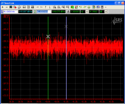
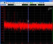
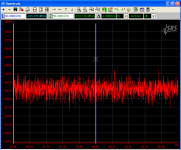
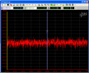
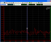
Run a quick test. Harmonics were measured for 20kHz 5Vrms (+14dBVrms) output signal loaded on 33Ohm resistor (around 0.75W at load). For IMD I mixed 20kHz and 21kHz signals, 2.5Vrms (+8dBVrms) each at output. Results you can see on the screenshots. If we go from absolute to relative levels, we will get -149dB for second and -157dB for third harmonics of the 20kHz signal. For IMD test it will be -162dB for 19kHz and 22kHz products, -161dB for 1kHz product.
There is no conclusion at the end. Just an improved by ~9dB results on higher output levels comparing to the old prototype.
Attachments
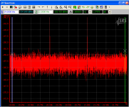
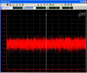
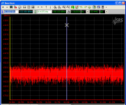
Same thing driving 16.5Ohm load. Just a little bit worse for the second harmonic at 20kHz. The rest is pretty much the same.
Attachments
Last edited:
Very Cool I love that driver chip!!!
Here is my version of a LT1210 with a LT1007 servo,
http://www.diyaudio.com/forums/soft...re-capacitor-impedance-graph.html#post3848338
I am sure it could be tweaked more but it works great as is!!")
jer
Here is my version of a LT1210 with a LT1007 servo,
http://www.diyaudio.com/forums/soft...re-capacitor-impedance-graph.html#post3848338
I am sure it could be tweaked more but it works great as is!!
jer
I haven't had it hooked up to a supply that delivers enough current to fully test its current capability yet, but I love it's very low THD and noise level.
As my plots show, it superseded my Gina24 sound card!!!
I just got some more to parallel a few of them.
I used it to plot the impedance of a primary winding of one of my ESL step up transformers and it worked like a charm!!!
jer
As my plots show, it superseded my Gina24 sound card!!!
I just got some more to parallel a few of them.
I used it to plot the impedance of a primary winding of one of my ESL step up transformers and it worked like a charm!!!
jer
Last edited:
No problems. Here it is.
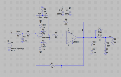
There is nothing new. Just shifted accents a little bit the way I wanted. It is possible to increase the loop gain even higher, but not sure if it will bring real benefits.
Used it without output filter during my testing, but in the real world it is required. Could may sense readjust values to elevate input impedance to 3.3k or around it.
Attachments
Thanks a lot, i'm far from your knowledge, but if i don't understand now all details, i'm learning easily when design interest me as i'm trying to understand harder. I didn't notice until now that there can be one "zobel//snubber" (however you call it) each side of this kind of output filter. For very high frequencies ?
What is the supply voltage in your test ?
What is the supply voltage in your test ?
This output filter was an attempt to optimize a decoupling of an amplifier output and damping of a cable and a driver resonance. This resonance frequency is usually not very high, around 1-2MHz.
Perhaps I can double check if those values are correct.
I was running it from +/-11.5V
Perhaps I can double check if those values are correct.
I was running it from +/-11.5V
Hi sergey !
Any news about this design ?
It seems that you made a proper design for it if i understand well (http://www.diyaudio.com/forums/head...edance-headphone-amp-project.html#post4374878). Would you mind sharing it ? A least the new shematic ?
Thanks !
Damien
Any news about this design ?
It seems that you made a proper design for it if i understand well (http://www.diyaudio.com/forums/head...edance-headphone-amp-project.html#post4374878). Would you mind sharing it ? A least the new shematic ?
Thanks !
Damien
- Status
- This old topic is closed. If you want to reopen this topic, contact a moderator using the "Report Post" button.
- Home
- Amplifiers
- Headphone Systems
- A composite with LT1210 - another way of doing it