Dear all,
I have a pair of Stax Lambda Pro Bias headphones, and two SRD 4 electret transformer drive units to which I have added a pro bias supply using some fiddly soldering. I am not 100% happy as the bass is poor and I currently have 2 boxes with wires joining them to supply my headphones. I suspect the bass issue is that I am being limited by the performance of the transformers and not the headphones.
For this reason I am thinking of building a headphone amplifier for my Stax headphones. After following the bidding on a popular auction site I have decided that although this approach will give me a nice box and after replacing the capacitors on such an amplifier I will have spent in the region of 300 Euro, even for a poorly thought of unit.
From looking a a list of Stax products the output voltages look like they range from 280V to 630V RMS with some thing like 400V RMS being a good target.
Some very cool designs exist and while I should like to go for an all solid state design for cost and reliability reasons I fear that suitable transistors are rare as hens teeth.
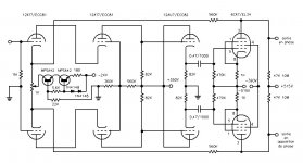
This search eventually led me to designs such as this note on the Stax SRM X. This started me thinking about using the 6SN7 as an output tube.
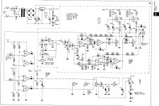
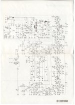
On a french forum I found the attached "ampli-casque-EL34.1.jpg" which looks like a better design than the SRM-X as it is using an extra buffer stage, but uses an EL34 and purely on subjective reasons I was thinking of avoiding pentodes as using valves was out of my comfort zone already.
After some time browsing that popular auction site, I saw a SRA 3S for sale, so I looked at the schematic which looks cheaper to build but this also uses obsolete transistors but looks like it could reduce the cost of an initial implementation.
So the questions I have:
0) Is their a lower cost option with parts likely to be available for 10 years I am missing?
1) Do people think the "6SN7GT B" which is currently in production is a good choice of output driver, the two designs I see it used in are 280V RMS, or should I go for some thing which supports a higher voltage like a EL34 even though its a pentode?
2) Should I be aiming for a higher output voltage than 280V RMS as provided by the SRM-X and SRA 3S?
3) The 2sc734 looks a very unremarkable transistor assume some thing like the BC639G will replace it easily or could you recommend a better substitution?
4) The SRA 3S uses 100uF capacitors around the current balance for the input transistors. I cant imagine this is the right solution in modern design, could this be replaced with a constant current supply?
5) Should I just ignore the SRA 3S design and use an alternative tube/valve driver circuit?
6) Do you know of better transistor circuits for driving triodes/pentodes that I could mix and match that would be better than using the SRA 3s circuit.
7) Have you heard any of these designs, or have opinions on what I should avoid?
I want a cheap design, with parts I can replace if they break, good bass response preferably with total cost of materials under 200 Euro if at all possible.
Thanks in advance
Owen
I have a pair of Stax Lambda Pro Bias headphones, and two SRD 4 electret transformer drive units to which I have added a pro bias supply using some fiddly soldering. I am not 100% happy as the bass is poor and I currently have 2 boxes with wires joining them to supply my headphones. I suspect the bass issue is that I am being limited by the performance of the transformers and not the headphones.
For this reason I am thinking of building a headphone amplifier for my Stax headphones. After following the bidding on a popular auction site I have decided that although this approach will give me a nice box and after replacing the capacitors on such an amplifier I will have spent in the region of 300 Euro, even for a poorly thought of unit.
From looking a a list of Stax products the output voltages look like they range from 280V to 630V RMS with some thing like 400V RMS being a good target.
Some very cool designs exist and while I should like to go for an all solid state design for cost and reliability reasons I fear that suitable transistors are rare as hens teeth.
This search eventually led me to designs such as this note on the Stax SRM X. This started me thinking about using the 6SN7 as an output tube.
On a french forum I found the attached "ampli-casque-EL34.1.jpg" which looks like a better design than the SRM-X as it is using an extra buffer stage, but uses an EL34 and purely on subjective reasons I was thinking of avoiding pentodes as using valves was out of my comfort zone already.
After some time browsing that popular auction site, I saw a SRA 3S for sale, so I looked at the schematic which looks cheaper to build but this also uses obsolete transistors but looks like it could reduce the cost of an initial implementation.
So the questions I have:
0) Is their a lower cost option with parts likely to be available for 10 years I am missing?
1) Do people think the "6SN7GT B" which is currently in production is a good choice of output driver, the two designs I see it used in are 280V RMS, or should I go for some thing which supports a higher voltage like a EL34 even though its a pentode?
2) Should I be aiming for a higher output voltage than 280V RMS as provided by the SRM-X and SRA 3S?
3) The 2sc734 looks a very unremarkable transistor assume some thing like the BC639G will replace it easily or could you recommend a better substitution?
4) The SRA 3S uses 100uF capacitors around the current balance for the input transistors. I cant imagine this is the right solution in modern design, could this be replaced with a constant current supply?
5) Should I just ignore the SRA 3S design and use an alternative tube/valve driver circuit?
6) Do you know of better transistor circuits for driving triodes/pentodes that I could mix and match that would be better than using the SRA 3s circuit.
7) Have you heard any of these designs, or have opinions on what I should avoid?
I want a cheap design, with parts I can replace if they break, good bass response preferably with total cost of materials under 200 Euro if at all possible.
Thanks in advance
Owen
Attachments
The SRA-3S is very much a product of its time and personally I'd build something more refined and with different tubes if you are venturing into the hybrid territory.
The 6SN7 is a fine tube and Stax are still using its sibling in their amps but it's not the best choice for this role. Low voltage rating (well for the normal type and the 6CG7) in this context means the tubes will misbehave. This is certainly true of the Stax amps and why Stax will move to the ECC99 for future amps. Not a perfect solution but the best tube in current production for this particular role.
While it's true that high voltage sand is disappearing quickly making solid state options harder, there are still some being made. Most are limited to +/-400V and not all are ideal due to high output capacitance but they will work. I doubt many of them will be around in 10 years though. When we released the KGSSHV design back in 2010 Toshiba said the 2SC4686A would be around for at least 5 years but it was dead in less than two.
So if you want something you can still service in 10 years easily, costs very little and works surprisingly well, then there is this:
Front end is ECC83 and the output can be 6CG7's, 6SN7, 6S4A or just what ever you want. Rudistor even built a version with EL34's but there is no way that works well without another stage being added. Only thing to take care with is the heater wiring as the two front end tubes need their own supply and so do the output tubes.
Thank-you for the information spritzer.
Particularly useful to mention " heater wiring as the two front end tubes need their own supply and so do the output tubes." It had never occurred to me this could be an issue, I guess their is potential for feed back issues here?
Sing X3 and X4 will be in anti phase I guess using a double triode such as the ECC99 or the "6SN7GT B" as cathode to header voltage can only be 200V?
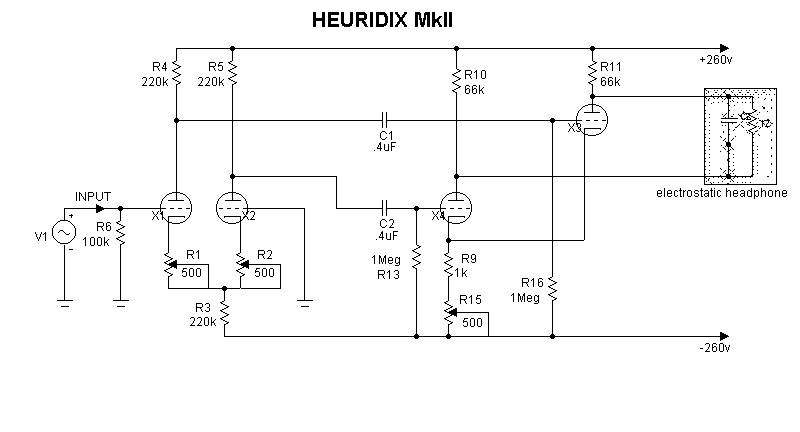
I had seen the "HEURIDIX MkII" design in my web browsing, and it looks very cheap to make, but was put off by the lack of feedback in the system. Because of this I assumed that the performance would be poor.
I had a look at the data sheets of the ECC99 and the "6SN7GT B" seem to have similar voltage limits.
ECC99 = 400 V Ua
6SN7GT B = 450 Maximum plate voltage.
Maybe I am reading the data sheet wrongly. This said the "HEURIDIX MkII" does look the cheapest solution to build, even if the cathode to hater voltage requires two different output tubes per channel.
Thanks again.
Particularly useful to mention " heater wiring as the two front end tubes need their own supply and so do the output tubes." It had never occurred to me this could be an issue, I guess their is potential for feed back issues here?
Sing X3 and X4 will be in anti phase I guess using a double triode such as the ECC99 or the "6SN7GT B" as cathode to header voltage can only be 200V?
I had seen the "HEURIDIX MkII" design in my web browsing, and it looks very cheap to make, but was put off by the lack of feedback in the system. Because of this I assumed that the performance would be poor.
I had a look at the data sheets of the ECC99 and the "6SN7GT B" seem to have similar voltage limits.
ECC99 = 400 V Ua
6SN7GT B = 450 Maximum plate voltage.
Maybe I am reading the data sheet wrongly. This said the "HEURIDIX MkII" does look the cheapest solution to build, even if the cathode to hater voltage requires two different output tubes per channel.
Thanks again.
why do you need the transistors to be available in 10 years? - suitably applied, properly derated they don't wear out in a human lifetime - MTBF for IXYS discrete MOSFET is in the centuries
buying the best Q available now will let you build an amp that will last through many ps recapping cycles, long beyond the time linear mains supply are expected to be outlawed by the Greens
buying the best Q available now will let you build an amp that will last through many ps recapping cycles, long beyond the time linear mains supply are expected to be outlawed by the Greens
why do you need the transistors to be available in 10 years? - suitably applied, properly derated they don't wear out in a human lifetime - MTBF for IXYS discrete MOSFET is in the centuries. Buying the best Q available now will let you build an amp that will last through many ps recapping cycles
I am no electronics engineer, but I am convinced you are correct about the lifetime of MOSFET's but I expect my electronics to die due to accidents. I don't want to worry about this.
Illustrates the issues of getting spares.When we released the KGSSHV design back in 2010 Toshiba said the 2SC4686A would be around for at least 5 years but it was dead in less than two.
Honestly I could just buy lots of spare transistors for the design, what ever it ends up being. That said I would then have to find the spare parts if they then break.
While I would rather a solid state design, all things being equal, I don't have the necessary skills to design a good high voltage amplifier all on my own. I can slightly modify others designs, but all the designs I find are using MOSFET parts are using parts that are no longer available.
Do you have a design that I could use to be a solution to this problem?
Hi,
there are quite a number of HV-MOSFETs and bipolars around for Headphone useage as the supply lines typically are much less than 1kV.
Like MOSFETs: 2SK1317, 2SK2225, 2SK2943, 2SK3746-48, IRFBG20
Like Bipolars: 2SC4630, 2SC5353, BUK456, BUX87
Lets not forget the very promising upcoming SIC/SIT technology: FSICBH057A120 (someone at Fairchilds must clearly be nuts to name a device like that), Rohm´s SCT2450KE (verylow cap)
And IXYS released a couple of very-HV transistors for up to 4kV like:
IXBF12N300, IXBH6N170, IXTH02N250, IXTH1N200P3, IXTP06N120P up to the 4.5kV types IXTF02N450HV and IXFT1N450.
Even HV-Depletion MOSFETs like: IXTP08N100D2 and IXTP1R6N100D2 may be on the radar.
There are several circuits circling the net and this forum.
You may also want to take a look at this site
With the above posted circuits of #1 and #2, I wonder about the high valued anode resistors of 47k and 66k the tube amps.
Say Your HPs capsule capacitance measures 100pF, then each Amp-half will see 200pF.
The Anode resistor limits the charging current through the capsule.
The uppper bandwidth limit is then defined by the formula F-3dB = 1/(2pi*RC).
For F-3dB = 30kHz and C(capsule) = 200pF this results in an R(anode) of ~27kOhms.
Now You very probabely won´t need a full power bandwidth of 30kHz, but 47k, resp. 66k certainly limit the bandwidth to well within the audible range.
A transistor amp utilizing a SEPP topology and feedback (or a ccs-loaded source-/emitter-follower like the above linked one) could offer much lower output impedance, hence a linear ampitude response beyond the audio frequency range.
The issues with transistors are imho rather to control the -and omit with the- generated heat, and of course the general dangers of high voltage applications.
jauu
Calvin
Hi Calvin,
Thanks for the useful advice.
Off the transistors you mentioned I could only find BUX87 from RS so high voltage transistors are a little harder to get than you might imagine.
I must admit to liking the JLH class A 10W amplifier and wonder if some similar design could be scaled up to make a very simple class A 450V amplifier?
Can I use a series of low voltage conventional transistors in series to provide a constant current load some how?
As I said its supply that drives me to tube/valves")
This said the BUX87 has nearly the same ratings as a 6SN7 at less than a 16th of the price.
When looking for suitable transistors how should I proceed?
Something like the BUL216 has much higher voltage rating than the BUX87. Is it too non linear? How do I tell its unsuitable from the data sheets?
I may make a STAX SRA 3S clone because its simple and then see if any other designs can beat it.
Thank you again
Best Owen
Thanks for the useful advice.
Off the transistors you mentioned I could only find BUX87 from RS so high voltage transistors are a little harder to get than you might imagine.
Nice looking circuits. Again transistor supply is a big issue for most of them. The ccs-loaded source-/emitter-follower is maybe what I would do if I could find the transistors.There are several circuits circling the net and this forum.
You may also want to take a look at this site
I must admit to liking the JLH class A 10W amplifier and wonder if some similar design could be scaled up to make a very simple class A 450V amplifier?
Yes a very strong argument here.With the above posted circuits of #1 and #2, I wonder about the high valued anode resistors of 47k and 66k the tube amps.
Say Your HPs capsule capacitance measures 100pF, then each Amp-half will see 200pF.
The Anode resistor limits the charging current through the capsule.
The uppper bandwidth limit is then defined by the formula F-3dB = 1/(2pi*RC).
For F-3dB = 30kHz and C(capsule) = 200pF this results in an R(anode) of ~27kOhms.
Now You very probabely won´t need a full power bandwidth of 30kHz, but 47k, resp. 66k certainly limit the bandwidth to well within the audible range.
A transistor amp utilizing a SEPP topology and feedback (or a ccs-loaded source-/emitter-follower like the above linked one) could offer much lower output impedance, hence a linear ampitude response beyond the audio frequency range.
Can I use a series of low voltage conventional transistors in series to provide a constant current load some how?
The issues with transistors are imho rather to control the -and omit with the- generated heat, and of course the general dangers of high voltage applications.
As I said its supply that drives me to tube/valves
This said the BUX87 has nearly the same ratings as a 6SN7 at less than a 16th of the price.
When looking for suitable transistors how should I proceed?
Something like the BUL216 has much higher voltage rating than the BUX87. Is it too non linear? How do I tell its unsuitable from the data sheets?
I may make a STAX SRA 3S clone because its simple and then see if any other designs can beat it.
Thank you again
Best Owen
check for low Cds, Crss these need to be as low as possible - a electrostat headphone may be only 100 pF and you really don't want to spend all of your power/current driving the output device parasitic C instead of the headphone
so just say no to multi Amp rated parts - the die are too big so they have too much parasitic C
this leaves us with very few suitable SS parts - mostly IXYS MOSFET and discontinued CRT driver BJT
so just say no to multi Amp rated parts - the die are too big so they have too much parasitic C
this leaves us with very few suitable SS parts - mostly IXYS MOSFET and discontinued CRT driver BJT
Hi,
You may find some of the transistors at Digikey.
For example the excellent ITH 02N250 in TO247 casing (also in SMD TO263 as IXTA and plus220SMD as IXTV).
With 50mA DC-SOA @1000V and 75°C, and extremely low output and reverse Capacitance, and sufficiently high transconductance, it should be a fine choice for ESL-HP-amps.
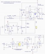
It could be used as cascode transistor for a modulated current source and as load CCS in a amp like shown in the attachement.
The Elektor article shows a nearly identical topology to the Sennheiser HP-amp.
Sennheiser working with BSP125 MOSFETs.
jauu
Calvin
You may find some of the transistors at Digikey.
For example the excellent ITH 02N250 in TO247 casing (also in SMD TO263 as IXTA and plus220SMD as IXTV).
With 50mA DC-SOA @1000V and 75°C, and extremely low output and reverse Capacitance, and sufficiently high transconductance, it should be a fine choice for ESL-HP-amps.
It could be used as cascode transistor for a modulated current source and as load CCS in a amp like shown in the attachement.
The Elektor article shows a nearly identical topology to the Sennheiser HP-amp.
Sennheiser working with BSP125 MOSFETs.
jauu
Calvin
Attachments
Last edited:
I use a MOSFET differential amplifier using 800 volt n channel mosfets and a 450 volt regulated power supply. I can't post a schematic, but the drain load is 13k per side. There is a minus 15 volt supply to provide about a 35 ma. current sink for the sources. Power dissipation is about 4 watts per fet and resistor. The diff amp is driven by a NE5532 opamp at some low gain to bring the output to a reasonable level for your driving source. The diff amp gives you the push pull phase shift you need.
Dear Calvin and Jaclement,
Thanks for the suggestions.
Oh yes it is available.
Sadly its a little expensive, more than the price of a triode!
So I have taken some inspiration form the circuits Calvin included and the good success Jaclement had with such a simple design.
I shall build a few, ideas and see how they all work. I have ordered a nice high voltage transformer and some high voltage capacitors.
I also ordered the "6SN7GT B" for a comparison as I think I will build a MOSFET and a valve based design and see which I like best.
I particularly like the idea of modding the opamp driven MOSFET with no output capacitor, as I have read (but don't know if it's true yet), that at such high voltages the capacitors "sing", maybe with a DC servo to set the voltage right.
Can I just use the "ITH 02N250" in place of the output MOSFET's in all of the designs Calvin posted or would I need to make many changes to bias?
Best regards
Owen
Thanks for the suggestions.
the excellent ITH 02N250 in TO247
Oh yes it is available.
Sadly its a little expensive, more than the price of a triode!
So I have taken some inspiration form the circuits Calvin included and the good success Jaclement had with such a simple design.
I shall build a few, ideas and see how they all work. I have ordered a nice high voltage transformer and some high voltage capacitors.
I also ordered the "6SN7GT B" for a comparison as I think I will build a MOSFET and a valve based design and see which I like best.
I particularly like the idea of modding the opamp driven MOSFET with no output capacitor, as I have read (but don't know if it's true yet), that at such high voltages the capacitors "sing", maybe with a DC servo to set the voltage right.
Can I just use the "ITH 02N250" in place of the output MOSFET's in all of the designs Calvin posted or would I need to make many changes to bias?
Best regards
Owen
even film caps can become "piezoelectric" when they have high DC bias (polarization dependent electrostriction)
but this depends on the construction - the plates have to be able to move - used to be a problem in old oscilloscope ps with audio frequency chopper supplies and oval Mylar caps - the oval shape doesn't allow for even winding pressure, worse some were wound on removable round mandrels and then squashed to oval shape
high tension wound, or bonded layers will have much less problem
the really paranoid could stack+parallel a few of the biggest, highest V rated NP0/C0G ceramic caps - a solid, void free, nonpiezo material - at considerable cost
but the concern in electrostat amp output DC blocking is probably overstated - you also need high AC too and its usually the case that you are using 100x the expected ES headphone Cload so the output caps only see 1% of the audio AC
Last edited:
Nice schematic, have similar going in my head for a while. I Like that idea about bunch of twin triode LTP´s with ccs in cathodes.Dear all,
I have a pair of Stax Lambda Pro Bias headphones, and two SRD 4 electret transformer drive units to which I have added a pro bias supply using some fiddly soldering. I am not 100% happy as the bass is poor and I currently have 2 boxes with wires joining them to supply my headphones. I suspect the bass issue is that I am being limited by the performance of the transformers and not the headphones.
Owen
On input side a Lundahl input trafo, wired as centertap for max symmetry. And endstage maybe ecc99 or bigger triodes, working into centertap choke.
Supply plus side grounded. Stators wired to choke ends. Lundahls interstages cost like plate chokes..so you can use that instead
Not a problem, since input trafos have 1500v insulation.
Plate choke will improve distortion-linearity, better than resistor. Not cheap tho

Last edited:
- Status
- This old topic is closed. If you want to reopen this topic, contact a moderator using the "Report Post" button.
- Home
- Amplifiers
- Headphone Systems
- Low cost Stax headphone amplifier