Any portable device that drives headphones will have an amp of some sort. As power consumption is all important, this could even be a Class D (switching) amp.
For something easy to build and that sounds great, why not try a TDA2822M chip. It doesn't come any easier than this and it will work on a wide range of supply voltage.
TDA2822M
For something easy to build and that sounds great, why not try a TDA2822M chip. It doesn't come any easier than this and it will work on a wide range of supply voltage.
TDA2822M
Nice Mossfet sweetness
I have built a few of these and they sound nice. Getting expensive for the
MPF-102 though.
JFET iPod preamplifier
I have built a few of these and they sound nice. Getting expensive for the
MPF-102 though.
JFET iPod preamplifier
Wow! Class D even. Never would have thought it but that makes sense with power consumption.
You are speaking my language Mooly. Thanks for the recommendation there.
EDIT: just saw your post sfltrack. I like the idea of JFETs (even simpler). I've got a bunch of JFETs (mostly J201 or similar) but I'm guessing they're too small to do what you have there. I don't know too much about hte MPF's.
This would be off topic (but same project), I want to take signal off of my mic preamp. I'm guessing I'd want to pull this signal before the output transformer or phase splitter (I want unbalanced, correct)?
second question:
Would I need to put a high impedance input buffer device (say an FET) before the TDA2822M chip so I wouldn't notice any signal loss due to loading the signal from my preamp? I'd hate to loose any sound quality due to feeding the monitor amp.
last question:
to mix 2 signals without bleed, I'd guess I'll need an opamp (or FET amp) channel per signal fed with maybe a pot right after this stage? Sorry if this is a simple question. I can picture the idea but have never seen it in a schematic.
Yes, unbalanced for these circuits. Whether you need a buffer or not depends on the preamp that would drive the headphone amp. If you used a 47k volume control on the headphone amp then any preamp should drive that kind of load many times over so I wouldn't foresee any problem there.
To mix two signals with no interaction really requires an opamp run in inverting mode.
Post #12")
http://www.diyaudio.com/forums/anal...ffering-two-signals-together.html#post3613722
To mix two signals with no interaction really requires an opamp run in inverting mode.
Post #12
http://www.diyaudio.com/forums/anal...ffering-two-signals-together.html#post3613722
Thanks Mooly, I saw your attachment in that post (and attached it here for simplicity) I can remove it if need be.
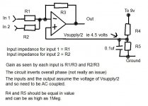
So both inputs go into the inverting side of an opamp via a resistor (R1 and R2). Wouldn't there be some crosstalk of the signals or interaction/loading between signal source 1 and 2? I guess if I use 1M resistors the input impedance would be high but then I'd have to use a huge feedback resistor to get gain and maybe noisy not sure there.
EDIT: sorry for the many questions. Mooly, you mentioned two signals having no interaction require an opamp, would an FET per input channel not provide the required isolation?
Attachments
Last edited:
There is no interaction what so ever and that is because of the way the inverting opamp configuration works. It makes the perfect mixer.
Basic theory... the opamp output will do whatever is needed to keep the difference between the two inputs at zero volts.
So signal wise there is nothing to measure or see at the inverting input and so no interaction or modulation of one signal interfering with the other. The output from the opamp is the perfect combination of the two applied signals.
If you just mixed resistively then you would get interaction.
I see you've edited the post
1meg is to high as you say, noise and hf roll of could be a problem.
The secret of the inverting stage having no interaction between inputs (and you can add as many inputs as you want to the mixer) is that the voltage on the opamp inverting input really is virtually (I say virtually to keep the theorists happy) zero all the time... that takes some getting used to and figuring out but its true. Scope it, measure it with a DVM if you apply DC voltages to the inputs... you won't measure anything on that point in the circuit but the output will be a true mix of the applied signals... however many inputs you add.
Use the rule I posted on how it works and put some numbers in and you will see how it works (remember to take the inversion into account in the calculation)
That's me done for today
Thanks for your insight. Wow, I'll have to test this out on a breadboard.
I had always heard opamp gain was R3/R1 and not vice versa. That almost struck me as an error in that diagram but I'm assuming that's not the case for some reason. No need to answer that Mooly but if anyone knows the why here.
I had always heard opamp gain was R3/R1 and not vice versa. That almost struck me as an error in that diagram but I'm assuming that's not the case for some reason. No need to answer that Mooly but if anyone knows the why here.
Hi,
FWIW the heaphone amps in a Walkman or MP3 are quite
specialised chips to allow the output to swing rail to rail.
Basically they are beefed up versions of low voltage op-amps
and like those, they have a common emitter output stage,
rather than the common collector emitter follower type.
The output stage has open loop gain which varies with
the load, but it all gets fixed in the end with feedback.
rgds, sreten.
e.g. see the AD820 op-amp data sheet.
Last edited:
In fact, the gain actually is -R3/R1. Input impedance is R1 - as outlined, the inverting input is a virtual ground here. You can calculate the whole shebang by assuming same current through R1 and R3 and applying the basic ideal opamp equations.
Inverting opamp as a headphone amp is not a new idea... the BTech BT928 (inverting w/ 5532) was a popular modding victim around here a decade ago. NJM4556, NE5532, NJM4580 should all work quite well. It's not a terribly low-noise config, since noise gain is equal to noninverting gain (i.e. R3/R1 + 1) and input impedance requirements often mean that R1 is big enough for its voltage noise to entirely swamp many a lower-noise opamp's contribution. (A 5532 approximately equals a 2.2k.)
That's not what anybody uses in a portable player though. Aside from the amp stages usually being integrated into codecs or even SoCs, they would be low voltage rail-to-rail affairs, typically supplied from lithium cells at 3.6-4 V down to regulated 1.8 V. For an idea what's current, here are some dedicated headphone drivers from Maxim, TI and AMS.
In fact, the gain actually is -R3/R1.
That's what I thought so does Mooly have the Gain formula inverted (a mistake/mistype)?
Attachments

That's what I thought so does Mooly have the Gain formula inverted (a mistake/mistype)?
If you read the original post you took the diagram from, (post #12)
http://www.diyaudio.com/forums/anal...ffering-two-signals-together.html#post3613722
and read the last sentence
- Status
- This old topic is closed. If you want to reopen this topic, contact a moderator using the "Report Post" button.
- Home
- Amplifiers
- Headphone Systems
- Simplest headphone amp circuit (something like you'd get in a walkman or MP3 player)?