I want to build a passive box to sum two headphone level outputs to one set of headphones. Basically, a mixer without level control. I've found this article which gives advice on blending sources: Simple mixer
I've purchased the jacks that I think I need
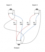
And I've put together a simple schematic that I think will work for me (attached.)
In my schematic, red is the left channel, blue is the right channel, and black is ground. This appears to be the way the jacks are pinned, so assuming that's correct, does this all look right?
I understand that I'll lose some signal level, and I'm not planning on using it for hi-fi listening or studio mixing. Thanks!
I've purchased the jacks that I think I need
And I've put together a simple schematic that I think will work for me (attached.)
In my schematic, red is the left channel, blue is the right channel, and black is ground. This appears to be the way the jacks are pinned, so assuming that's correct, does this all look right?
I understand that I'll lose some signal level, and I'm not planning on using it for hi-fi listening or studio mixing. Thanks!
Attachments
...does this all look right?
Almost, but not quite. That would work for line level signals but probably not for headphone outputs. The problem is that looking back into your circuit from the headphones you would see 5k, those two 10k resistors more-or-less in parallel. That is way too high of an output impedance for any headphone. Most of the output voltage would be dropped across the 5k combo leaving very little for your headphones, even if they are up at 600 ohms impedance.
You could try 100 ohm resistors instead of 10K. If you had a 50 ohm headphone that would result in a 50/50 voltage divider. You would loose half the output voltage in your resistor combo. If your headphones were 600 ohm things would be much better. A lot less loss across the 100 R mixing resistors.
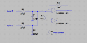
Here is another idea if you would be willing to use an amplifier. The input section of the O2 amplifier could be modified just like you have drawn to make a mixer. The input impedance to your headphone outputs would stay a stable 10K ohm, plus the amp would have low output impedance to drive your headphones.
The circuit is an op amp summer. For details see here:
Operational amplifier applications - Wikipedia, the free encyclopedia
Attachments
Last edited:
I see a typo already in the circuit I posted. ") You would only need one 220pF cap. That forms a filter with the 274R resistors to keep RF noise above the audio band out of the amplifier. Noise like that wouldn't come from the headphone outputs, but might be picked up in the connecting cables acting like antennas if anything leaks through the cable sheild.
You would only need one 220pF cap. That forms a filter with the 274R resistors to keep RF noise above the audio band out of the amplifier. Noise like that wouldn't come from the headphone outputs, but might be picked up in the connecting cables acting like antennas if anything leaks through the cable sheild.
You also couldn't likely drop down to, say, 10R for the mixing resistor rather than 100R. The problem here is that the two headphone outputs are not in phase since they are different signals. At any given instant in time one output could be swinging high, say +3V, while the other is swinging low, like -3V. That would produce [+3V - (-3V)] / (10R + 10R) = 300mA just in current passing from one headphone output to the other, not through the headphones. That would be quite a bit of current for a lot of headphone outputs, especially given the headphone current in addition.
One more thing to watch out for is connecting the shields together. Assuming both headphone outputs are being powered by batteries or from AC via separate wall transformers you would be OK. But if they are coming from the same piece of equipment there is a chance of a ground loop through a common power supply. To find out, take a DMM and measure both AC and DC from the shield on one headphone out to the other. There shouldn't be any significant voltage.
You would only need one 220pF cap. That forms a filter with the 274R resistors to keep RF noise above the audio band out of the amplifier. Noise like that wouldn't come from the headphone outputs, but might be picked up in the connecting cables acting like antennas if anything leaks through the cable sheild.You also couldn't likely drop down to, say, 10R for the mixing resistor rather than 100R. The problem here is that the two headphone outputs are not in phase since they are different signals. At any given instant in time one output could be swinging high, say +3V, while the other is swinging low, like -3V. That would produce [+3V - (-3V)] / (10R + 10R) = 300mA just in current passing from one headphone output to the other, not through the headphones. That would be quite a bit of current for a lot of headphone outputs, especially given the headphone current in addition.
One more thing to watch out for is connecting the shields together. Assuming both headphone outputs are being powered by batteries or from AC via separate wall transformers you would be OK. But if they are coming from the same piece of equipment there is a chance of a ground loop through a common power supply. To find out, take a DMM and measure both AC and DC from the shield on one headphone out to the other. There shouldn't be any significant voltage.
Last edited:
Almost, but not quite. That would work for line level signals but probably not for headphone outputs. The problem is that looking back into your circuit from the headphones you would see 5k, those two 10k resistors more-or-less in parallel. That is way too high of an output impedance for any headphone. Most of the output voltage would be dropped across the 5k combo leaving very little for your headphones, even if they are up at 600 ohms impedance.
You could try 100 ohm resistors instead of 10K. If you had a 50 ohm headphone that would result in a 50/50 voltage divider. You would loose half the output voltage in your resistor combo. If your headphones were 600 ohm things would be much better. A lot less loss across the 100 R mixing resistors.
Here is another idea if you would be willing to use an amplifier. The input section of the O2 amplifier could be modified just like you have drawn to make a mixer. The input impedance to your headphone outputs would stay a stable 10K ohm, plus the amp would have low output impedance to drive your headphones.
The circuit is an op amp summer. For details see here:
Operational amplifier applications - Wikipedia, the free encyclopedia
Probably it would be better to use a NJM4556, since the NJM2068 probably won't be very happy driving a low-impedance load.
- Status
- This old topic is closed. If you want to reopen this topic, contact a moderator using the "Report Post" button.