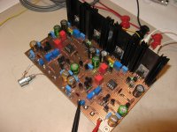
Hi. Here on of my newest project. It is a fully dual mono all discrete FET headphone amplifier in Class-A. Real Class-A at 100ma per supply, and channel. With supplies of +/-24V it is 9.6W in Class-A (200ma * 48V = 9.6W). It is cooking 
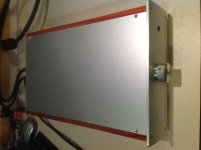
It sounds superb, perfectly silent with dual fully discrete low noise regulators with CRC pre-filters. The case was made by Front Panel Express, side wood panels in exotic Padouk wood with oil finish.
The circuit is DC coupled, we no coupling capacitor in the signal path. A servo takes care of the small circuit thermal drift.
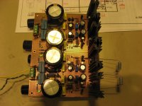
Here the prototype pictures
It sounds superb, perfectly silent with dual fully discrete low noise regulators with CRC pre-filters. The case was made by Front Panel Express, side wood panels in exotic Padouk wood with oil finish.
The circuit is DC coupled, we no coupling capacitor in the signal path. A servo takes care of the small circuit thermal drift.
Here the prototype pictures
Attachments
Last edited:
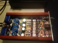
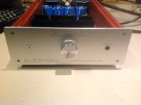
And the completed amp. It is using great parts everywhere Furutech AC power inlet, Non-magnetic line noise filter (aka Ayre es filter), Low noise vibration decoupled dual toroid transformers, Philips/Vishay huge pre-filter caps, Wima, Nichicon KG/Muse, CDE and Vishay caps, Caddock MK132 and Vishay CMF55 film resistors, Noble volume pot, Canare power & Mogami audio cables, 6N single crystal copper hookup wires, Cardas and Amphenol connectors and the classic blue led power on indicator.
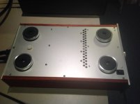
Even the bottom is nice, with vibration decoupling feet, laser trim ventilation holes and concealed power-on switch.
Even the bottom is nice, with vibration decoupling feet, laser trim ventilation holes and concealed power-on switch.
Attachments
Last edited:
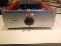
The power section is all assembled point-to-point. I did my own PCB. Ventilation holes can be seen on the back. You cannot see it but there is bitumen vibration absorbing pad under the top cover. Front and Back views. It is real statement amp, top of its class. Difficult to do better I guest...
Attachments
Last edited:
Sorry no schematic. This is a design is copyright and I cannot disclose any details. This circuit can also be used as a preamp, single-ended or balanced. Indeed the supply can be lowered to +/-18V, but the regulator will then dissipate more heat. Input of the regulators are +/-31V. I may try that to lower the amp dissipation. It is a balance between amps and regs.
Sorry no schematic. This is a design is copyright and I cannot disclose any details. ...
Why post it on a _diy_ site then ?
Why post it on a _diy_ site then ?
Free Advertising?
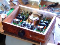
Here is a photograph of it open but unfortunately no schematic since it is also copyright.
Is the photograph copyrighted as well ?
One is never too careful
Jacques

- Status
- This old topic is closed. If you want to reopen this topic, contact a moderator using the "Report Post" button.
- Home
- Amplifiers
- Headphone Systems
- My new headphone amp