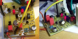
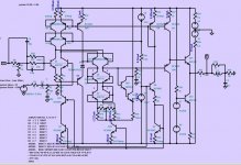
Here's a jpeg of the circuit.
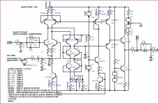
I think the problem is the output network, I was trying to stabilize the amplifier for a maximum 10nF capacitive load and that requires either a big output resistor (~100 ohms) or a big compensation C.
So the compensation needs some fixup. Any suggestions?
I think the problem is the output network, I was trying to stabilize the amplifier for a maximum 10nF capacitive load and that requires either a big output resistor (~100 ohms) or a big compensation C.
So the compensation needs some fixup. Any suggestions?
Attachments
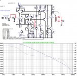
Ok I changed the output network and compensation, it now has a loop compensation C from output to inverting input and an RC at the VAS output. Spice predicts 50° phase margin (see picture). I'm still a noob at this poles/zeroes stuff so no idea what the resistor in series with the VAS compensation C does but it did improve things 
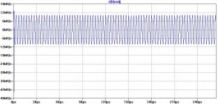
It now has 10.4V/us slew rate (tested with 1Vp 300K input signal).
Any suggestions on how to come up with an ideal combination of R's and C's to compensate this thing?
It now has 10.4V/us slew rate (tested with 1Vp 300K input signal).
Any suggestions on how to come up with an ideal combination of R's and C's to compensate this thing?
Attachments
Last edited:
- Status
- This old topic is closed. If you want to reopen this topic, contact a moderator using the "Report Post" button.