That's very interesting and makes me even more curious why the O2 seems to sound better on AC power. You would think it should be the opposite since the batteries should be less noisy then the AC power supply.You are right, I thought that at one time based on the math. But it turned out that I was wrong about that one.
I did some actual testing after that and found the battery impedance didn't make any difference at all. Kind of surprised me.I ran several low frequency sine waves into the O2 and measured the output voltage on AC and on batteries (the output voltage was setto be low enough to work on either batteries or AC). The net result: no difference at all in output voltage either way. Not even a tiny difference, I measured pretty carefully. What that must be saying is that the NiMH battery impedance is much lower than I thought it was from the graphs I found via Googling that day.
So it is OK to build your O2 up the standard way.
I have (2) O2 amps, one with batteries and one without, it has an integrated ODAC inside.
I have done many back and forth listening tests and blind testing, I could never tell any real world differences between AC power or batteries.
I also got a lab DC supply an old Lamdba and tried it with "clean" DC power when I was building them awhile back.
If your hearing differences would you tell me what music, album and track etc I would like to try this again etc...
Thanks
Alex
agdr
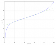
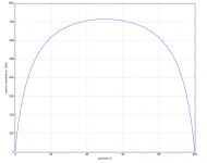
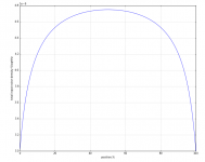
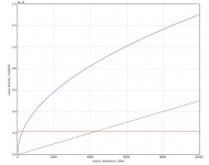
I mentioned earlier that it is possible to use linear potentiometer and achieve some sort of emulation of exponential characteristic. Here is some estimation of gain vs position, input noise using LM4562 based buffer after the pot, plus S/N graph assuming signal is 2Vrms (only for the buffer+pot). I also made a "source resistance" plot this case to see what would be maximum DC offset caused by input bias current.
On the first graph the green reference lile is an exponential function with look straight on semilog plot.
Attachments
Have a look at OPA(2)209. It has nice combination of current and voltage noises and low bias current. On the down side GBW is not so great, but not too far for OPA140 ect. It is quite linear, especially on a lite load.
Also large phase margin can be quite forgiving.
Nice part.
However, if you look at the datasheet there is a graph comparing the OPA209 current noise to OPA827 and it clearly shows that above 2K source resistance, the current noise of OPA209 will be above the noise of the source resistance itself. On the other hand, with the OPA827 the current noise is so low that above 2K source resistance you are only limited by the noise generated by the source resistance itself.
To make it short, below 2K source resistance OPA209 is better than OPA827 and above 2K source resistance OPA827 is better than OPA209.
Another thing that is important is that since agdr is using the O2 front end gainstage it will absolutely dominate the total amplifier noise.
The difference between an output buffer stage using the 1.1nV/Hz LME49990 compared to using the 4nV/Hz OPA827 is less than 0.5dBv total amplifier noise.
To make it simple :
Input gain stage = high performance BJT input Opamp.
Output buffer= high performance JFET input Opamp.
Last edited:
I have (2) O2 amps, one with batteries and one without, it has an integrated ODAC inside.
I have done many back and forth listening tests and blind testing, I could never tell any real world differences between AC power or batteries.
I also got a lab DC supply an old Lamdba and tried it with "clean" DC power when I was building them awhile back.
If your hearing differences would you tell me what music, album and track etc I would like to try this again etc...
Thanks
Alex
I don't recall the exact tracks since I haven't really messed around with it for quite some time but I do remember it was most noticeable with bass heavy electronic music. I would play some music on battery power and while it was playing I'd plug in the AC power and there was a small but noticeable difference in bass quality. I remember thinking I must be imagining things until I read that AGDR had a similar experience.
What do you think of some of the newer opamps from AD? There's a few that look interesting like the ada4898 and ada4627 but they may be a bit to power hungry for a battery powered amp like the O2.
ada4627 voltage noise is too high.
ada4898 current noise is too high.
But these aren't bad parts at all and they may sound absolutely wonderful in real life.
Real world noise at the levels we are talking about here would be unhearable by anyone.
I am just looking at them from the point of view of what gives me the best specifications.
Nice part.
above 2K source resistance, the current noise of OPA209 will be above the noise of the source resistance itself.
I can not agree with that. Thermal noise of 2.5k resistor, for instance, will be around 6.5nv/sqrtHz, voltage noise of OPA209 is 2.2nV/sqrtHz and the current noise over the impedance in this case will be around 1.25nV/sqrtHz.
Current noise just can not dominate in this case even if it would be 5 times higher.
Last edited:
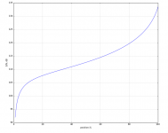
Here is a plot of noises of the OPA209 vs thermal noise of the source.
Blue - thermal noise, green - input current noise * source resistance, red - voltage noise.
The other thing that spec does not state what fraction of the current noise is corelated for the inputs.
Blue - thermal noise, green - input current noise * source resistance, red - voltage noise.
The other thing that spec does not state what fraction of the current noise is corelated for the inputs.
Attachments
I have a feeling the lme49990+lme49600 will be hard to beat as far as specs are concerned, have you seen the measurements over in the "Wire" thread? Pretty impressiveada4627 voltage noise is too high.
ada4898 current noise is too high.
But these aren't bad parts at all and they may sound absolutely wonderful in real life.
Real world noise at the levels we are talking about here would be unhearable by anyone.
I am just looking at them from the point of view of what gives me the best specifications.

The Wire is pretty awesome. I don't know what it is, but for some reason I prefer it to the O2 (even with the booster) but it's closer than without the booster. Before the booster, the O2 seemed to lack "air" and seemed "dry" or boring. With the booster, that's gone. The OPA1641 seems to be a well liked opamp in the diy community.
While LME49990 with LME49600 can be a good option, especially because of high GBW of the first one, it is not the only way of achieving a good result. With a little bit of effort and attention to detail a handful of NE5532 may give a sub-ppm level of distortion while driving around a hundred of mW into a load.
Also just putting a good (or the best?) spec opamp into a circuit does not guarantee a good result. A lot of things which look secondary in a circuit very often require an attention.
Also just putting a good (or the best?) spec opamp into a circuit does not guarantee a good result. A lot of things which look secondary in a circuit very often require an attention.
Last edited:
While LME49990 with LME49600 can be a good option, especially because of high GBW of the first one....
Actually, for stability reasons it is wise to choose an Opamp that has a significantly lower GBW than the LME49600 buffer.
You want you buffer IC to be significantly fasten than the input Opamp to keeep group delay and phase shifts to a minmum. Otherwise you could end up with an oscillatiing circuit.
I am not denying that something like "The Wire" works and works really well.
But in general such a configuration is not advised.
Actually, for stability reasons it is wise to choose an Opamp that has a significantly lower GBW than the LME49600 buffer.
You are right about possible issues in case if no measures were taken to maintain stability. A simple second order network, something like agdr has in his design, will help. Of course the values must be tweaked to use it with completely different opamp, but idea remains the same.
In case of "the Wire" I'm a little bit surprised that there are no issues, especially considering absence of any damping at the output. Perhaps noise gain of 2 or higher helps somewhat.
Last edited:
You are right about possible issues in case if no measures were taken to maintain stability. A simple second order network, something like agdr has in his design, will help. Of course the values must be tweaked to use it with completely different opamp, but idea remains the same.
In case of "the Wire" I'm a little bit surprised that there are no issues, especially considering absence of any damping at the output. Perhaps noise gain of 2 or higher helps somewhat.
I personally use a 100pF cap from OPA827 inverting input to OPA827 output in my own OPA827+BUF634 composite circuit for stability reasons. It might not be needed but I would rather be safe than sorry.
With regards to "The Wire" I too am a little surprised there are no issues.
But it is quite possbile that of the many "The Wire" built sofar some builders might have issues with capacitive loading of which they are not aware. It could be oscillating at above 50 MHz without people noticing it if it is just a low level oscillation on top of a sinewave. Most people do not have the required equipment to measure it at those frequency, if they have any equipment at all.
I personally use a 100pF cap from OPA827 inverting input to OPA827 output in my own OPA827+BUF634 composite circuit for stability reasons. It might not be needed but I would rather be safe than sorry.
It is always possible roll off the gain faster than just with a first order if you want. This way there will be no sacrifice in the loop gain in audio band while keeping unity gain frequency low enough to be safe.
Yeah I agree with you guys. I think it is a really good idea to have compensation in that buffer feedback loop. Especially with the LME49600 gain "bump" at 80MHz that Sergey888 pointed out a while back.
So far that second order network has just been rock solid. I've hit it with all sorts of reactive loads and looked at the output with a 200MHz scope. No oscillations at all.
I don't recall the exact tracks since I haven't really messed around with it for quite some time but I do remember it was most noticeable with bass heavy electronic music. I would play some music on battery power and while it was playing I'd plug in the AC power and there was a small but noticeable difference in bass quality. I remember thinking I must be imagining things until I read that AGDR had a similar experience.
It sure has seemed that way to me a few times, that the bass on the O2 just sounds better on AC. I don't think it was listening bias either because each time it happened things went in the other directions - I had to look to see if the O2 was on batteries or AC (I really didn't remember) when the effect occured. Then I would plug and unplug the AC, like Fsatsil did, and it sure seemed to me that bass was better on AC power, Noticeably better, not just a little bit.
So far I don't have an electrical explanation for it! Or whether it is all in my head.
One difference was that my Vrms output tests at different low frequencies (20Hz to 400Hz or so) were all done with sine waves. Maybe real music is affecting things somehow. This is a great example of why "how it sounds" is so important along with "how it measures", in my view of things.I really thought I was onto something with that output impedance of the voltage regulators vs. the impedance looking back into the NiMH batteries. That is one thing that definitely changes with the O2 AC cord is unplugged.
I was able to install a new socket for u3 and the O2 is back up and running. I connected the booster board and no more turn on/off thump and the dc offset is down to acceptable levels. It is unmeasurable on the left channel and .8mv on the right channel which leads me to believe there is still something not right with that channel. I'm gonna try giving the board a good cleaning with a toothbrush and some alcohol and see if it helps. Either way I plan to to build a new O2 since I already ordered a new pcb.
Yeah do give the O2 PCB a good scrub, both sides. If that doesn't do it then it pretty much has to be the O2's 2.2uF coupling cap for that channel gone bad and leaking current. There can be a few mV of voltage from the O2 gain stage across that volume pot. If the cap leaks that may be enough to cause the voltage you are measuring going into the booster board.
Last edited:
agdr
There are a few things you should not forget about bjt input opams.
1. There are a lot of them with input bias current compensation, so you may get an appropriate bias voltage with given DC impedances.
2. They have higher current noise, especially those with lower voltage noise, as their input stage runs on a higher current. Using them even with 10k pot may end up with current noise dominating. LME49990 is a good example.
Have a look at OPA(2)209. It has nice combination of current and voltage noises and low bias current. On the down side GBW is not so great, but not too far for OPA140 ect. It is quite linear, especially on a lite load.
Also large phase margin can be quite forgiving.
That LME49990 will probably come down to a tradeoff between THD+N and noise if someone uses it in their booster board. From the datasheet graphs it looks like the THD+N is a whole order of magnitude better at 20KHz than the OPA140, OPA827, and even that OPA209 (interesting chip, BTW!). But like you say the current noise is likely to be higher, plus there is that increased DC output offset voltage with the bipolar chip.
From the datasheet graphs it looks like the THD+N is a whole order of magnitude better at 20KHz than the OPA140, OPA827, and even that OPA209 (interesting chip, BTW!). But like you say the current noise is likely to be higher, plus there is that increased DC output offset voltage with the bipolar chip.
There is a solution for that, but you will not like it!
One of the main reasons why LME49990 has better THD performance is that it has one of the highest GBW among "audio" chips, as a result you have a lot of feedback depth around an output stage or buffer. The other way of getting this is using the output buffer that has gain itself. A current feedback amplifier with sufficient output current can be a good option. In this case you get an additional freedom in choosing the front end part.
Beside that, THD graphs in datasheets are usually made for 2k load or something like that, while LME49600 is somewhat higher impedance load. While output of an opamp remains in class A, it is usually more linear. I suspect this will be true for your design.
- Home
- Amplifiers
- Headphone Systems
- O2 headamp output booster PCB