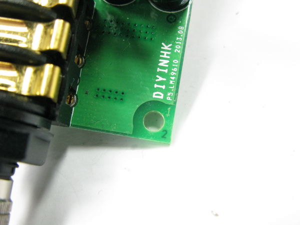
4 layer PCB The corner 1234 letter is printed on different layer to make sure the pcb manufacturer do not reverse the middle two layer arrangement in factory
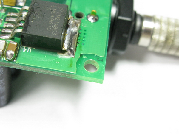
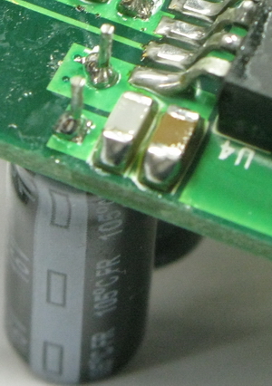
Many people blame against the distance of decouple distance, and yes, it do make a different. Total 4000uf panasonic low esr capacitor in 1MM (yes! 1MM decouple distance) see the pic with my component arrangement it should be the only way to fulfill the 2000V/μs slew rate and max. 750mA output current of lme49610 before trigger it's short circuit output protection
Testing with the Tchaikovsky 1812 overture, the cannon fire is much more real than ever before. For comparison, real world cannon fire can be heard in many festival.
Gold plated headphone socket has much lower contact resistance, the sound output is much more clear, non-audiophiles can also hear the difference.
This is only a prototype, please don't blame on the soldering quality
Any comment and suggestion are welcome
The corner 1234 letter is printed on different layer to make sure the pcb manufacturer do not reverse the middle two layer arrangement in factory
Many people blame against the distance of decouple distance, and yes, it do make a different. Total 4000uf panasonic low esr capacitor in 1MM (yes! 1MM decouple distance) see the pic with my component arrangement
it should be the only way to fulfill the 2000V/μs slew rate and max. 750mA output current of lme49610 before trigger it's short circuit output protectionTesting with the Tchaikovsky 1812 overture, the cannon fire is much more real than ever before. For comparison, real world cannon fire can be heard in many festival.
Gold plated headphone socket has much lower contact resistance, the sound output is much more clear, non-audiophiles can also hear the difference.
This is only a prototype, please don't blame on the soldering quality
Any comment and suggestion are welcome
Last edited:
- Status
- This old topic is closed. If you want to reopen this topic, contact a moderator using the "Report Post" button.