Hi there,
I am working on building a copy of the headphone version of the Moskido amplifier that was posted on The Tube Cad Journal some time ago here - MOSKIDO Amplifiers
In particular, this circuit -
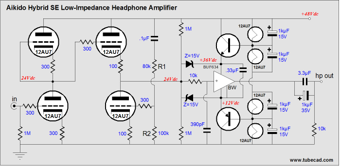
I understand the operation of the circuit and from what I can see, it should work. I plan on making my own pcb using smd parts, which will be done soon.
Before i do though, was wondering if you guys could offer any suggestions? Attached is my altium schematic, will post the pcb shortly and can give the entire project file to you if you want. let me know!
Thanks in advance!
I am working on building a copy of the headphone version of the Moskido amplifier that was posted on The Tube Cad Journal some time ago here - MOSKIDO Amplifiers
In particular, this circuit -
I understand the operation of the circuit and from what I can see, it should work. I plan on making my own pcb using smd parts, which will be done soon.
Before i do though, was wondering if you guys could offer any suggestions? Attached is my altium schematic, will post the pcb shortly and can give the entire project file to you if you want. let me know!
Thanks in advance!
Attachments
I'm a bit puzzled about what advantage(s) the more 'complicated' heater arrangement adds to the cct - I wouldn't , particularly when it ties in directly to the output buffer - any details before you do a pcb, or perhaps optional links/pads?
An other thing you could consider with this cct is to develop a good quality +/- 24 volt supply and use an input cap to V1 in order to get rid of the 'problem' output electro cap - a 'better sounding' compromise, IMHO.
... my 2 cents,
An other thing you could consider with this cct is to develop a good quality +/- 24 volt supply and use an input cap to V1 in order to get rid of the 'problem' output electro cap - a 'better sounding' compromise, IMHO.
... my 2 cents,
The BUF634 can't take 48 V, but the resistance of the heaters conveniently provides 12 V and 36 V in steady state, so they used those as a regulator reference. I hope the buffer has better PSRR than the input circuitry.I'm a bit puzzled about what advantage(s) the more 'complicated' heater arrangement adds to the cct - I wouldn't , particularly when it ties in directly to the output buffer - any details before you do a pcb, or perhaps optional links/pads?
Generally speaking you're right, but great caution is required when adapting single-supply circuits to split supply, or else you may open up a PSRR can of worms. Here's an example that I discussed recently. I would assume this circuit to have very similar issues on a split supply.An other thing you could consider with this cct is to develop a good quality +/- 24 volt supply and use an input cap to V1 in order to get rid of the 'problem' output electro cap - a 'better sounding' compromise, IMHO.
"Simplicity" probably is the answer here. It would require another transformer secondary, rectifier etc.Why not use more voltage to the valves and use an independent source for the buf? more voltage to the valves will give a more linear operation
You're right though. This would also be an opportunity to use fancier rail filtering on the high supply (which would have to supply a fair bit less current), while the BUF could be operated from a +25.2 or +/- 12.6 V supply with rearranged heaters (12.6 V is the nominal heater voltage for a 12AU7 and easily obtained by shifting a 12 V reg up with a silicon diode).
Last edited:
Thanks for the information!
Just as an update, i did in fact build the entire circuit with the values specified in the first post.
Interesting nobody noticed that the heaters take 12.6v in series (so two tubes would drop 25.2 volts total) but the circuit has 48v going into the two tubes. Anyway i added some power resistors in series with the heaters to bring the heater voltage to 12.6 per tube.
As for performance, the amplifier clips horribly when supply voltage APPROACHES 48v.
Best functionality is at 30v it seems. not really sure what the story is but will look into it.
Any ideas?
- Status
- This old topic is closed. If you want to reopen this topic, contact a moderator using the "Report Post" button.
- Home
- Amplifiers
- Headphone Systems
- Moskido Hybrid headphone amplifier! Help needed