Dynamic range can be shifted downwards as needed. Without this ability, source SNR requirements may become very strict.
Are you referring to an analog pot?
I hear talk about how digital attenuators (like on your computer) remove information from the signal unless they are set at 100%. I'm confused about this (I'm an analog guy from way back) and would appreciate some clarification on this topic, if possible.
Thank you.
All the time.Are you referring to an analog pot?
That's a different story, but for one thing, a software-operated volume control does not necessarily mean digital attenuation. It may also control a PGA (programmable gain amplifier) in the analog stage. PGAs essentially are an electronic version of a stepped attenuator with gain-switchable amplifier, employing FETs as switches. I'd say your average onboard or MP3 player codec uses one. Fancy DACs typically rely on digital attenuation instead, as THD and SNR targets are hard to hit otherwise. PGAs allow for dynamic range management as outlined earlier, however, so they may have lower noise floor at low levels (unless their amplifiers are hissy MOS jobs).I hear talk about how digital attenuators (like on your computer) remove information from the signal unless they are set at 100%. I'm confused about this (I'm an analog guy from way back) and would appreciate some clarification on this topic, if possible.
If carried out at high enough precision, digital attenuation is absolutely nothing to worry about. A moderate amount usually is undetectable even when done straight in 16 bit, which is hardly ideal. Done in 24 bit or 32-bit float with 24-bit output or proper dithering to 16 bit, it's totally transparent. Obviously this only applies to PCM audio. A digital data stream like AC-3 or DTS audio would be corrupted when treated like that, as many people found out when trying to stream these things to their home theater receiver.
Many problems in digital audio today are related to high, not low levels. Overshoot in lossy codecs, intersample overs, stuff like that. A pinch of digital attenuation may mean that the following playback chain is safely kept out of clipping, without having to rely on graceful intersample over handling. If you are making use of ReplayGain, this usually introduces enough attenuation anyway.
If anyone is still following this thread what was the DC offset if changing the original values of gain setting resistors to lower values . If someone has already said I apologies . Anyone got a theory about OK DC offset for headphones ? I was hoping 1 to 2 mV would be OK . A commercial headphone chip says absolute maximum 400 uV. One thread on a headphone site recommended something like 47 and 240 R as NJM 4556 has plenty of drive current .
About DC offset-
DC offset will cause diaphragm to be slightly displaced "in" or "out" of its normal resting position consequently reducing max. excursions.Anything less than 20mV is acceptable, but if you are using very sensitive low impedance h/p than strive for offsets less than 5mV. Higher impedance/low sensitivity h/p are more immune to DC offsets.
As for gain resistors values I use this for reference(exhaustive details/comments but must read)-
NwAvGuy: Cmoy eBay Headphone Amp (with wrong value gain resistors)
NwAvGuy: Cmoy With Gain (with corrected gain resistors values)
If you are planning to build a simple CMOY, reduce the gain to as low value as possible(2X-4X range). I've achieved offsets < 2mV for JRC4556 based CMOYs.
Last edited:
I know this is an old thread but i was looking for a decent clone kit for my SR80s and found this one. DIY RA1 Headphone Amplifier Kit Power AMP JRC4556AD GE | eBay
I know it's cheap but i have a better pot and if i like it i might try some Solen caps for the input like the original uses.
Any thoughts people? it seems quite decent but i'm still a novice when it comes to circuit design/layout.
Cheers
I know it's cheap but i have a better pot and if i like it i might try some Solen caps for the input like the original uses.
Any thoughts people? it seems quite decent but i'm still a novice when it comes to circuit design/layout.
Cheers
Uhh... when the actual circuit conforms to the schematic in post #2, it isn't a buffer. (Rf/Rg values merely are a lot higher than they should be for best noise and distortion performance.)
It was the one that NwAvGuy got that had a 470 ohm resistor installed instead of a 470k - who messed up there is anyone's guess.
It was the one that NwAvGuy got that had a 470 ohm resistor installed instead of a 470k - who messed up there is anyone's guess.
oh, then it seems the clones that i can quickly find, have it all wrong.
"Resistors 464R *2" (also printed on the board)
DIY RA1 Headphone Amplifier Kit Power Amp JRC4556AD Z96 | eBay
different board - same value(you can see it on the last pic)
https://de.aliexpress.com/item/RA1-..._7&btsid=8ae2556c-61f7-47ae-a6ad-a2ca09b5dd94
well, then so much for "...and the values for the components seem to be right aswell" from my first post.
Same 'original' schematic here (post 7) Building the Perfect Cmoy for Grado SR 225s
ECM (post 9) advises us to use the original values.
I'll probably get a kit to try anyway, hope it works better than the dual chip Cmoy I've currently got. (LM6171 & LME49720) just ain't doing it for me.
ECM (post 9) advises us to use the original values.
I'll probably get a kit to try anyway, hope it works better than the dual chip Cmoy I've currently got. (LM6171 & LME49720) just ain't doing it for me.
Last edited:
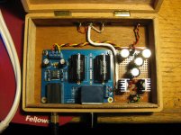
This thread takes me back, first DIY headphone amp i put together. It ended up as a cigar box amp which i used for a while.
I wouldn't get too caught up on the resistor values unless you want to be faithful to the original Grado design, if not google some cmoy calculators which will help you pick some better combinations to tailor the gain level to what you need.
Pity the kit i bought is no longer available as it was much cheaper. You could also just build it yourself on some protoboard like most cmoys designs.
Attachments
Very nice build there. I'm lazy so like a pre made board and they are usually lower noise in operation if attention is paid to grounding etc. I fancy trying the original values, at first anyway. Two 9V battery's should last a bit longer than my current cmoy which can only use/charge one. I like a self powered amp, small desk top style for use around the house. Just need a bit more current for my SR80's i recon.
- Home
- Amplifiers
- Headphone Systems
- grado ra1 clone