Hi everyone
I am considering to build a no gain head amplifier to use together with my phone.
I was planing to test this design Class A MOSFET Headphone Driver | HeadWize.
Do you think it will improve the sound from my headphones?
I use my phone as source (Nokia 920) and a couple of Denon headphones.
Thinking of buying some new headphones if the headamp turns out good.
Hi
I have decided to move on with this project.
I have only a basic understanding of electronics so there are some question that i hope someone can help me with.
First it seams that the MOSFET used in the design IRF 513 is no longer available.
I think i have some IRF 610 at in a box somewhere, would these be possible to use?
Or can anyone suggest a good replacement for IRF 513?
I plan to replace the R4 with a CCS according to the sugestion from JimT.
Would it be possible to use a LM317 CCS with a potentiometer?
I am not sure if it could deliver enough current.
What other modifications is recommended?
That looks interesting, i am thinking doing something similar together with IRF610. What kind of OP-amp do i need for this, is more or less anyone ok or do it need some special characteristics.
Found this website of a head amp with IRF610, DIY IRF610 MOSFET Class-A Headphone Amplifier Project
Found this website of a head amp with IRF610, DIY IRF610 MOSFET Class-A Headphone Amplifier Project
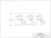
Input capacitors are probably a good idea too, since "Lin" and "Rin" are biased at +10 volts.Here is something I built. Works great!
You can eliminate the virtual ground and use output caps if you wish.
Input capacitors are probably a good idea too, since "Lin" and "Rin" are biased at +10 volts.
I know it isn't noted on the schematic, but input ground
and output ground are the same. With output/input ground
being virtual and the inputs being referenced to virtual
ground, there is no offset voltage at the inputs
That looks interesting, i am thinking doing something similar together with IRF610. What kind of OP-amp do i need for this, is more or less anyone ok or do it need some special characteristics.
Found this website of a head amp with IRF610, DIY IRF610 MOSFET Class-A Headphone Amplifier Project
There is no op amp.
There is a TLE2426 rail splitter...is that what you mean?
That looks interesting, i am thinking doing something similar together with IRF610. What kind of OP-amp do i need for this, is more or less anyone ok or do it need some special characteristics.
Found this website of a head amp with IRF610, DIY IRF610 MOSFET Class-A Headphone Amplifier Project
You will be happy with Giovanni Militano's improvement over the original Szekeres. Remember that class A does take a large heatsink. The second post mentions an improvement to the biasing network for the mosfet. I do have this on mine, but it would not be needed with a regulated supply. I plan to build a Salas SSLV for mine, but have been spending my time outside enjoying the summer.
Have fun
Jim
Jim
Here is something I built. Works great!
You can eliminate the virtual ground and use output caps if you wish.
That's a very cool circuit. I'm not a fan of virtual grounds, but using the voltage regulators as CCS's is very clever. (I know it's nothing new.)
I've heard that you can use a voltage regulator as an audio amplifier. I never tried it, but I can see how it would work. I don't know if it would work very well or not.
This circuit could easily be built by a novice on a perfboard.
Last edited:
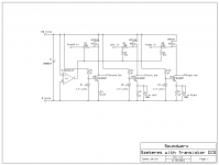
I also designed one with a transistor CCS as well.
I have not built this one.
I matched my MOSFETs, and with the timmers,
you can adjust the output offset to almost zero.
After it warms up (a few minutes), offset drifts very little.
Mine was built on perfboard and an old AMD Athlon heat
sink. With an 18 volt supply, it only ran warm.
Offset was under 10mV at startup and settles to less
than 5mV when warmed up.
Attachments
I've heard that you can use a voltage regulator as an audio amplifier. I never tried it, but I can see how it would work. I don't know if it would work very well or not.
Like this?
Attachments
Like this?
Yes, but the op amp buffer and CCS are icing on the cake. That is very nice.
The one I saw had no buffer or CCS. It was just a voltage regulator with a couple of resistors.
I also designed one with a transistor CCS as well.
I have not built this one.
I matched my MOSFETs, and with the timmers,
you can adjust the output offset to almost zero.
After it warms up (a few minutes), offset drifts very little.
Mine was built on perfboard and an old AMD Athlon heat
sink. With an 18 volt supply, it only ran warm.
Offset was under 10mV at startup and settles to less
than 5mV when warmed up.
That's a very nice, basic circuit. Is the transistor CCS better than the voltage regulator one, or not?
That MOSFET follower sure seems popular around here. It goes against my grain though; I am from the Walt Jung school of thought; I like to control everything precisely with feedback, caveats and all. In fact I have never employed discrete FETs of any kind in my circuits. When I went to school FETs were just being introduced into industry. I have used FET input op amps though; including the CA3140 which was about as good as it gets for audio filter circuits (tone controls) back in the day. This was way before the 5532/5534.
I know that zero feedback buffers have their merits, but on paper they look terrible. It's results that count though so don't label me a hater.
The one I saw had no buffer or CCS. It was just a voltage regulator with a couple of resistors.
I built output stage only from J.Broskie 24V Aikido schematic:
24V Aikido Line Stage and Headphone Amplifier
Just 2 x LM317 and 2 resistors, sounded really good.
I built output stage only from J.Broskie 24V Aikido schematic:
24V Aikido Line Stage and Headphone Amplifier
Just 2 x LM317 and 2 resistors, sounded really good.
Thanks for this. That is ridiculously simple and versatile too. I have seen a few circuits like this and kind of scoffed at them. I should give it a try. I already have evil plans.
I'm glad you mentioned the switching power supplies. I have a stack of servers that I got out of an electronic recycling drop off (along with a Marantz receiver that only cost $1.00 to fix and a Sony CD player that only needed cleaning and lube of the moving parts
 ) and have a whole bunch of parts for high power switching supplies. In fact, I was thinking about using some of them for a power amp supply. I think you could filter the noise out.
 You could build some really small (physically) amplifiers with some of this stuff is what I'm thinking. I also have a bunch of fans of various sizes from my plunders. I realize that the switching supplies do get pretty hot.
Last edited:
New idea, i was planing thinking about building something like this. This a concept i have seen used a lot, but not as a head amp.
I plan do use a bias of about 1amp so that i will run mostly in class A, if my understanding of how it works is correct. Could be wrong as i am not good with electronics.
I am also nut sure what values to use for the resistors R3 and R4, any suggestions how calculate that?
Will this work?
I plan do use a bias of about 1amp so that i will run mostly in class A, if my understanding of how it works is correct. Could be wrong as i am not good with electronics.
I am also nut sure what values to use for the resistors R3 and R4, any suggestions how calculate that?
Will this work?
An externally hosted image should be here but it was not working when we last tested it.
- Status
- This old topic is closed. If you want to reopen this topic, contact a moderator using the "Report Post" button.
- Home
- Amplifiers
- Headphone Systems
- MOSFET follower to my phone