I do not have the parts to breadboard prototype with yet, only battery is ordered so far. ~2 weeks to get that. Free time lately is a luxury so progress into this project may be slow.
Im designing a daughterboard for the o2 that will run on a single 2000 mAh LiPo cell, and still hopefully leave room for the odac to fit.
Lets start with the battery i chose:
3 7V 2000mAh Lithium Battery Rechargeable Polymer Li Po for Nav MP3 GPS B 853460 | eBay
The dimensions are almost perfectly sized for fitting inside the 'battery compartment' and it has a built in protection IC so i dont need one.
MCP73841-420I/UN Charge management controller is fairly self-explanatory:
http://ww1.microchip.com/downloads/en/DeviceDoc/21823D.pdf
I will be running a inverting boost converter set at +-15v output, then using the O2's regulators to drop it to normal 12-ish volt operating voltage. this should filter out any switching noise etc etc. I will bypass the mosfet low voltage cutoff as it is not useful anymore when being fed with a boost converter. Might need to use two separate boost converters to get the current i need instead of an monolithic one
When/if i get to the stage of installing the odac ill rig it to charge off of either usb or the (converted to 12vdc) external supply.
The only thing thats going to be annoying is the battery managment ic's are all surface mount. I am having difficulty finding a high-ish current inverting boost converter in dip format, so i ultimately need to make my own pcb design. 'Dead Bug' until then
I have a friend that offered to help me hand etch a pcb but if there ends up being at least a few people interested (maybe with a protection IC included in the design) i would get the pcb formally run off and sell enough to make up my additional costs.
Last edited:
You are going to have significant IV losses through the + - 12V regulators with that configuration. (15V - 12V) * (24mA) * 2 = 144mW that you're dissipating at idle. That's the listed DC idle current using just the batteries that doesn't take into account the quiescent current of the regulators. All of this gets worse once you actually start driving a load. It should also be noted that these losses are absent when using the dual 9V batteries since the regulators are not needed.
There will also be switching losses from the boost / inverting converter. Do you know what the conversion efficiency will be for the positive and negative rails (each one is different) over the expected range of current given your 3.2-4.2V LiPo input? I'd guess that 80% is optimistic.
Lets estimate that the 3.7V * 2000mAh battery gives you 7400mWh of energy. 7400mWh * 80% = 5920 mWh.
Lets estimate that the two default 9V * 250mAh * 2 batteries give you 4500mWh.
Just to be able to match the dual 9V batteries, the LiPo solution needs to be able to run for 9hrs. 9h * 144mW from before is 1300mWh, and that's at idle! 5920mWh - 1300mWh= 4620mWh. That 1300mWh that you turned into heat at idle is going to blossom into a much uglier number when you start driving something. As you can see, there are big issues here that need to be addressed if you want the LiPo powered solution to be advantageous over two 9V batteries.
Last edited:
you have a good point on the dissipation losses on the regulators, I had switching noise in my head and not efficiency when i considered doing it that way. Probably much better off with outputting 12v directly. A bunch of the boost converters i was looking at earlier were claiming over 88% efficiency but that is probably for low current needs.
Never thought it would be a easy project. Thank you for the well thought out critique
Never thought it would be a easy project. Thank you for the well thought out critique
To minimize the power wasted I'd recommend putting LDOs (low-dropout-regulators) on your board after the boost / inverting controllers as you will still need a way to prevent switching noise from getting into the audio power rails. Set the output of the DC-DC converters to just above/below (V_out +- V_dropout) of the positive and negative LDOs. The linear regs used in the O2 have dropout voltages of 2V and 1.3V which is horrible for battery powered-usage. This way, you'll minimize the power wasted in the linear regulators since the voltage drop across the regulator can be made very small with LDOs. One thing to watch out for in this solution is the turn on transient. If you power everything on at once, you'll get uneven rise of the positive and negative rails, which can be dangerous for anything connected to the outputs. You'll need to figure out a way to delay activation of the LDOs until the voltages coming out of the DC-DC converter(s) have stabilized.
Last edited:
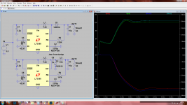
I noticed that when i was simulating some inverting controllers in spice, quite a bit of time difference between settling of each rail. simplest but not the best solution is perhaps to leave the dead battery protection circuit in place, this would prevent premature powerup and thus dc offset?
I think i found a controller that is suitable. it even was designed to permit configurable undervoltage lockout which would remove the need for a battery protector in all cases.
http://cds.linear.com/docs/en/datasheet/3580fg.pdf
http://cds.linear.com/docs/en/datasheet/3580fg.pdf
Attachments
Last edited:
regulators:
negative:
http://media.digikey.com/pdf/Data%20Sheets/Texas%20Instruments%20PDFs/UCC284-x_384-x.pdf
positive:
http://www.onsemi.com/pub_link/Collateral/NCP4629-D.PDF
with such a high switching frequency, i somewhat doubt it will be necessary tho. ill see how it goes without in prototype unless its strongly recommended against. Might also be useful to use potentiometers in place of feedback resistors so its possible to dial in the voltage you want
Last edited:
Losses on these designs are definitely something to consider. I've built a number of headphone amps using boost converters to generate a true +/- rail and have managed to maintain 10hour+ run times.
My most recent amp is using a TPA6120A2 headphone output driver with a MC33078 used as a input buffer. The amp is using a 2200mah 3.7v li-po. Pretty close to the spec you chose and I'm achieving 15+ hours avg. run time by employing a simple feedback circuit from the headphone outputs to vary the boost converter voltage output. +/- 6v until the positive voltage swing at the headphone jack reaches 3.5v then the circuit changes the boost converter's feedback loop to push the output to +/- 12v.
Unless you are driving lower ohm headphones pretty loud it never "shifts" out of the lower voltage range and nearly halves the idle current draw until the extra headroom is required. Higher ohm loads would of course coax it out of the low voltage output mode more often.
As far as the LDO's following the boost converter. I generally run between 1.2 and 2mhz switching frequencies then filter some of that high frequency noise with ferrite beads. Some of it makes it through to the headphone output but it's a very low level. less than a couple millivolts of ripple.
The boost regulator I've been using for the higher powered amplifier designs is the LT3579. datasheet links below.
The idle current draw at the battery on the TPA6120 based amp is 98mA with the boost converter at +/- 6v and 172mA at +/- 12v. With no load on the boost converter output power consumption is 11mA so the converters are pretty easy going on quiescent power consumption.
TPA6120
http://www.ti.com/lit/ds/symlink/tpa6120a2.pdf
MC33079
http://www.st.com/web/en/resource/technical/document/datasheet/CD00000474.pdf
LT3579
http://cds.linear.com/docs/en/datasheet/35791f.pdf
This is the battery charge/management chip I use. It's a Qfn-16 package. not all that diy friendly if you aren't used to small surface mount work
BQ24072
http://www.ti.com/lit/ds/symlink/bq24072.pdf
Last edited:
Nice points, Amperage.
The adaptive regulation is interesting. What are you using in the feedback loop to prevent the DC-DC output basically toggling very fast at audio frequencies if the headphone output voltage is swinging above/below 3.5V? There would have to be some sort of envelope detector with hysteresis built in I would think...
The adaptive regulation is interesting. What are you using in the feedback loop to prevent the DC-DC output basically toggling very fast at audio frequencies if the headphone output voltage is swinging above/below 3.5V? There would have to be some sort of envelope detector with hysteresis built in I would think...
Nice points, Amperage.
The adaptive regulation is interesting. What are you using in the feedback loop to prevent the DC-DC output basically toggling very fast at audio frequencies if the headphone output voltage is swinging above/below 3.5V? There would have to be some sort of envelope detector with hysteresis built in I would think...
A diode prevents negative voltages from discharging the circuit and a small capacitor charges and keeps the mosfet turned on for a short period after the voltage falls coming from the headphone output. The value of the capacitor and circuit leakage will obviously change the "on" time but in my particular application it holds the higher voltage level for approximately 5 seconds before the mosfet turns back off. I posted the circuit a while back in this thread and a later addon that gave a visual indication if it was operating in low or high power mode (power light pulses on and off when in low power mode).
http://www.diyaudio.com/forums/headphone-systems/235536-audio-controlled-voltage-mod.html
I've been running the circuit in a couple of amps for a while and measured the output on the scope looking for odd transients from the voltage shift. At worst from dead silent to a really loud burst there is a bit of clipping on the first half of the wave while the voltages come up from the DC-DC converter but it's inaudible. During normal listening there generally isn't such abrupt volume changes and the voltage shifts well in time to prevent clipping of any sort.
I got most of the parts in but i will need to design and have a pcb fabricated to do testing. I will work on that on and off over the next few weeks as i get time to do so. Meantime i have a soundblaster ZxR coming later this week that by chance has a tpa6120 so i will get to try out just how well it can run my high impedance headphones and i can go from there in my designs, perhaps instead of a upgrade for the o2 i will be essentially building a 6120 amp
really cool feedback circuit you got there amperage
really cool feedback circuit you got there amperage
Last edited:
I got most of the parts in but i will need to design and have a pcb fabricated to do testing. I will work on that on and off over the next few weeks as i get time to do so. Meantime i have a soundblaster ZxR coming later this week that by chance has a tpa6120 so i will get to try out just how well it can run my high impedance headphones and i can go from there in my designs, perhaps instead of a upgrade for the o2 i will be essentially building a 6120 amp
I quite enjoy the sound from my 6120 amps. It's certainly not the easiest on power consumption but it's capable of enough power output to brute force even the greediest of headphones. One modification I did make vs the recommended circuit configuration in the datasheet was to use 5ohm output resistors.. I haven't run into any stability issues at all with a number of diff loads and it's a much more acceptable output impedance for low resistance headphones.
reading through the datasheet earlier, i recall reading that the output resistors were to protect the 6120 from capacitive outputs and short circuits. since the datasheet cites using it as a pre-amplifier this is for the situation where the following stage is protected from dc offsets using a input capacitor, and for headphone usage can be reduced to 1 ohm or even omitted?
reading through the datasheet earlier, i recall reading that the output resistors were to protect the 6120 from capacitive outputs and short circuits. since the datasheet cites using it as a pre-amplifier this is for the situation where the following stage is protected from dc offsets using a input capacitor, and for headphone usage can be reduced to 1 ohm or even omitted?
I haven't tried completely eliminating it. The 6120 is a high speed op amp and as such is pretty sensitive to layout and oscillation issues. The chip itself has output short circuit protection so the resistors are mainly to protect it from load capacitance (even headphones have some small amount of capacitance). You can always add pads for the resistors on the pcb layout and bridge them just to test.
Just sampled my headphones on the integrated tpa6120 amp in my sound card. plenty of volume. I think i might be indeed be making my project tpa6120 based instead of o2.
That soundcard is running the 6120 Very conservatively also. If you check the specs here you can see even with 600ohm load it's rated for 2Vrms output. Not sure how they claim 80mW output into 600ohm. The tpa6120 is capable of it but when driven at +/- 12v. 2Vrms isn't going to do it
Creative Sound Blaster Z Sound Card Review | techPowerUp
that's running a MAX97220AThat soundcard is running the 6120 Very conservatively also. If you check the specs here you can see even with 600ohm load it's rated for 2Vrms output. Not sure how they claim 80mW output into 600ohm. The tpa6120 is capable of it but when driven at +/- 12v. 2Vrms isn't going to do it
Creative Sound Blaster Z Sound Card Review | techPowerUp
the ZxR is completely different hardware
Creative Sound Blaster ZxR Review - Closer Look
contrast between the two pcb's is interesting. the Z looks like barely anything on it in comparison =P
The software has a high gain setting, but specifically says not to use it on anything but 600 ohm headphones, and that the other setting is for up to 300 ohms(mines closer to 300 ohms)
contrast between the two pcb's is interesting. the Z looks like barely anything on it in comparison =P
The software has a high gain setting, but specifically says not to use it on anything but 600 ohm headphones, and that the other setting is for up to 300 ohms(mines closer to 300 ohms)
Last edited:
- Status
- This old topic is closed. If you want to reopen this topic, contact a moderator using the "Report Post" button.
- Home
- Amplifiers
- Headphone Systems
- O2 LiPo Daughterboard