Here is something you don't see everyday.  It occured to me that the desktop amp I've got going on in another thread could be chopped down and massively parallel LME49990's used for the output buffers. The LME49990s are relatively cheap these days at $2.50 each and have great performance, at least on the data sheet.
Going with using 1% of the 24ma maximum output current into 600R for balancing current would be 3.32R or so balancing resistors.
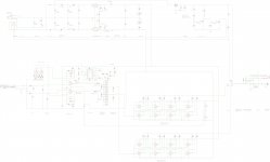
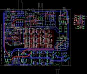
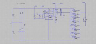
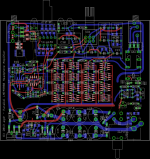
The layout below is just something I threw together quickly to see if it would even fit on a 80x100mm PC board (B2-080 case) and sure enough, looks like it does. 80x100mm gets the cost down enough to go 4 layer, with a groundplane under the LME49990 buffers and a boatload of decoupling caps at the power pins. 12Vac power transformer (wall wart) input so as not to exceed the 20V max on the LT1963A, so +/-12Vdc rails. The circuitry out to the side is the clipping detect circuit which could probably fit under the board.
Still uses two LME49990 chips for the gain stage / bass boost. If someone wanted to go direct DC coupled with no coupling caps in the path the DC offset of the LME49990s is probably low enough. Just leave out the 12 4.7uF film coupling caps in the middle and jumper one set of PCB cap holes on each channel to pass the signal along. Still has a 1K pot in the middle for low Johnson noise, something that wouldn't work if the pot was in front due to source loading.
I don't know if I'll try fabbing it or not, but if one of you layout wizards out there beat me to it I would probably buy a board. I'm curious how it would sound. The data sheet seems to show 0.000005% THD with an 8Vrms swing into 600R with +/-15V rails, for a single chip, if I'm reading that graph correctly. That would be 13mA rms for a single chip. This guy has 8 chips per channel to feed lower impedances.
It occured to me that the desktop amp I've got going on in another thread could be chopped down and massively parallel LME49990's used for the output buffers. The LME49990s are relatively cheap these days at $2.50 each and have great performance, at least on the data sheet. Going with using 1% of the 24ma maximum output current into 600R for balancing current would be 3.32R or so balancing resistors.
The layout below is just something I threw together quickly to see if it would even fit on a 80x100mm PC board (B2-080 case) and sure enough, looks like it does. 80x100mm gets the cost down enough to go 4 layer, with a groundplane under the LME49990 buffers and a boatload of decoupling caps at the power pins. 12Vac power transformer (wall wart) input so as not to exceed the 20V max on the LT1963A, so +/-12Vdc rails. The circuitry out to the side is the clipping detect circuit which could probably fit under the board.
Still uses two LME49990 chips for the gain stage / bass boost. If someone wanted to go direct DC coupled with no coupling caps in the path the DC offset of the LME49990s is probably low enough. Just leave out the 12 4.7uF film coupling caps in the middle and jumper one set of PCB cap holes on each channel to pass the signal along. Still has a 1K pot in the middle for low Johnson noise, something that wouldn't work if the pot was in front due to source loading.
I don't know if I'll try fabbing it or not, but if one of you layout wizards out there beat me to it I would probably buy a board.
I'm curious how it would sound. The data sheet seems to show 0.000005% THD with an 8Vrms swing into 600R with +/-15V rails, for a single chip, if I'm reading that graph correctly. That would be 13mA rms for a single chip. This guy has 8 chips per channel to feed lower impedances.Attachments
Last edited:
Here is what LT Spice comes up with for the massively parallel LME49990 headamp using TI's LME49990 sim model.
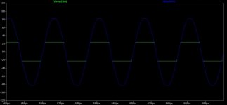
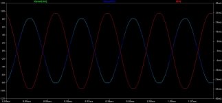
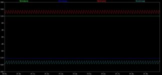
The first plot is with a single LME49990 output buffer feeding a 32R load (green plot, left scale). The blue is the output of the gain stage feeding the 1k pot, also a LME49990, feeding the 1K pot (the 1k attenuation resistor is jumpered). I've run the peak input voltage soure up to the onset of output clipping to find out what the model predicts for the +/-12Vdc supply rails. The red on the righthand scale is the current through one chip's balancing resistor, the per-chip current.
The results match up very well with the datasheet, which lists a worst case output voltage swing of 12Vdc with +/-15Vdc rails 3Vdc down from the rails), powering a 600R load. Here with 12V rails we can extrapolate to a max swing of around 12 - 3Vdc -9Vdc. The sim shows clipping out of the gain stage, with the 1k load at about 8.2Vdc. The single chip output into the 32R clips at 2.4V, a gallant try! The sim parameters are in the plot names, 20kHz 3.45Vpeak input in this case.
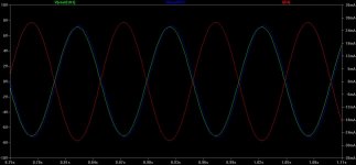
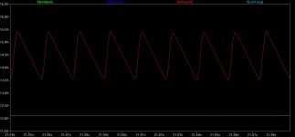
Now with the 8 output chips in parallel the sim plot looks amazingly good. The output of the 8 chips is clipping just slightly behind the gain stage at 8.0 and 8.2 respectively. But - is there smoke coming out? 8V peak would be 5.6Vrms, leaving about 6.4Vrms across each chip. The per-chip current is 32mA peak or 22.6mA rms. The dissipation in the chip is then 5.6Vrms x 22.6mA rms = 126mW, if I've done that right, which should be within the dissipation profile for the package including quiescent. So no smoke.
But the total dissipation over the 8 chips is 8 x 126mW = 1watt! 2 watts total over both channels (16 chips).
The next plot is the 8 buffer 32R load (plus 390pF in parallel on all these for cable capacitance) but at 10Hz to check that the 6 caps coupling caps on each channel are doing their thing. The simulation doesn't like to converge at low frequencies with clipping so I've had to back the input voltage down to 3.0V from 3.45 for convergence, but note that at 3.0V there is no clipping yet. Things at 10Hz are working as they should be.
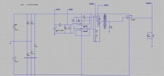
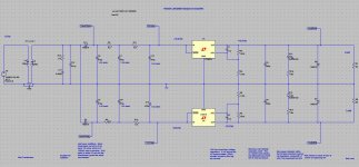
The final plot is the power supply using the LT1963A and LT3015 sim models. Predicts about 4mV of ripple with a 200mA per channel load, well within the PSRR of the LME49990 chips to deal with. The bottom of the ripple sawtooth is about 1.5Vdc above the output voltage, and the LDOs only needs about 0.5Vdc drop, so that leaves about a volt of wiggle room for power mains fluctuations (about +/-10Vac back on the primary side).
The first plot is with a single LME49990 output buffer feeding a 32R load (green plot, left scale). The blue is the output of the gain stage feeding the 1k pot, also a LME49990, feeding the 1K pot (the 1k attenuation resistor is jumpered). I've run the peak input voltage soure up to the onset of output clipping to find out what the model predicts for the +/-12Vdc supply rails. The red on the righthand scale is the current through one chip's balancing resistor, the per-chip current.
The results match up very well with the datasheet, which lists a worst case output voltage swing of 12Vdc with +/-15Vdc rails 3Vdc down from the rails), powering a 600R load. Here with 12V rails we can extrapolate to a max swing of around 12 - 3Vdc -9Vdc. The sim shows clipping out of the gain stage, with the 1k load at about 8.2Vdc. The single chip output into the 32R clips at 2.4V, a gallant try! The sim parameters are in the plot names, 20kHz 3.45Vpeak input in this case.
Now with the 8 output chips in parallel the sim plot looks amazingly good. The output of the 8 chips is clipping just slightly behind the gain stage at 8.0 and 8.2 respectively. But - is there smoke coming out?
8V peak would be 5.6Vrms, leaving about 6.4Vrms across each chip. The per-chip current is 32mA peak or 22.6mA rms. The dissipation in the chip is then 5.6Vrms x 22.6mA rms = 126mW, if I've done that right, which should be within the dissipation profile for the package including quiescent. So no smoke. But the total dissipation over the 8 chips is 8 x 126mW = 1watt! 2 watts total over both channels (16 chips).
The next plot is the 8 buffer 32R load (plus 390pF in parallel on all these for cable capacitance) but at 10Hz to check that the 6 caps coupling caps on each channel are doing their thing. The simulation doesn't like to converge at low frequencies with clipping so I've had to back the input voltage down to 3.0V from 3.45 for convergence, but note that at 3.0V there is no clipping yet. Things at 10Hz are working as they should be.
The final plot is the power supply using the LT1963A and LT3015 sim models. Predicts about 4mV of ripple with a 200mA per channel load, well within the PSRR of the LME49990 chips to deal with. The bottom of the ripple sawtooth is about 1.5Vdc above the output voltage, and the LDOs only needs about 0.5Vdc drop, so that leaves about a volt of wiggle room for power mains fluctuations (about +/-10Vac back on the primary side).
Attachments
-
 3.45Vpeak input at 20kHz - 2.5x gain - 1 LME49990 into 32R + 390pF circuit.jpg178.4 KB · Views: 1,515
 -
 3.45Vpeak input at 20kHz - 2.5x gain - 1 LME49990 into 32R + 390pF plot.jpg37 KB · Views: 1,357
 -
 3.45Vpeak input at 20kHz - 2.5x gain - 8 LME49990 into 32R + 390pF circuit.jpg124.8 KB · Views: 1,331
 -
 3.45Vpeak input at 20kHz - 2.5x gain - 8 LME49990 into 32R + 390pF plot.jpg54.3 KB · Views: 349
 -
 3.0Vpeak input at 10Hz - 2.5x gain - 8 LME49990 into 32R + 390pF plot.jpg58.1 KB · Views: 195
 -
 power supply circuit.jpg124.7 KB · Views: 316
 -
 power supply plot.jpg53.6 KB · Views: 306
 -
 power supply plot closeup.jpg44.9 KB · Views: 214
Last edited:
the heaviest load in headphones I know of are the hifiman orthos - if you take clipping free 120 dB SPL as a audiophile amp goal then 6 Wrms are required into 50 Ohms
requiring ~ 25 Vpk, 500 mApk ampltude
bridged parallel op amps could get you there - my cascaded, paralleled TPA6120 with 6x op aqmps per channel can do it
bridged, the TPA6120 would only require 2x parallel - and give considerable current reserve
I use a multiloop with OPA627 feedback wrapped around the TPA - which are also delivering V gain inside the loop, further linearizing the input op amp by requiring less
Vswing as well as buffering the load
the TPA chips have TI's power pad for external heatsinking
the TPA6120 are way cheaper per W, per mA output
jcx - the TPA6120 is a good chip! 0.0001% THD into 600R load if I'm reading the sheet correctly. But that would be lower with your loop around the chip. The only hiccup is that required 10R output resistor for stability, but that is a moot point for higher impedance phones and probably a lot of lower impedance cans. If you've paralleled them that effective output impedance looking back into the port is probably lower too. Good design!
Last edited:
Cload isolation needed with amost any 100 MHz op amp/buffer
unless the data sheet specificially calls out "C-Load Stable"
LME49990 datasheet:
so that really isn't a differentiating feature - except for the lack of guidance with the LME on the value of series R - they do show a recommended load network
there's no difficultly using series L to decouple Cload - could be air core, toroid if you really worried about magnetics linearity
the L can be small since it only has to reach |10-20| Z in the 10s of MHz
I use lossy ferrite smt bead with I rating 5-20x the op amp capabillity - haven't seen any distortion when measuring with ESI Juli@ yet
unless the data sheet specificially calls out "C-Load Stable"
LME49990 datasheet:
Capacitive loads greater than 100pF must be isolated from
the output. The most straight forward way to do this is to put
a resistor in series with the output. This resistor will also prevent
excess power dissipation if the output is accidentally
shorted.
so that really isn't a differentiating feature - except for the lack of guidance with the LME on the value of series R - they do show a recommended load network
there's no difficultly using series L to decouple Cload - could be air core, toroid if you really worried about magnetics linearity
the L can be small since it only has to reach |10-20| Z in the 10s of MHz
I use lossy ferrite smt bead with I rating 5-20x the op amp capabillity - haven't seen any distortion when measuring with ESI Juli@ yet
Last edited:
jcx - good point! I did see that 100pF load issue and figured the 3.32R on each chip would go some distance toward isolating it, but like you say they really don't give any guidelines. And the spice sim would be useless for something like that. Would just have to build it an do a bunch of measuring with various loads.
They also list that under the "stability" heading, then spend their time talking about settling time, like it is more of a transient response or overshoot issue, which is a common result of load C.
In fact, there is a question I'll bet you would know the answer to. I was pondering this one this afternoon and couldn't figure it out. If a single chip is rated to directly drive 100pF, then would 8 in parallel (with the balancing resistor) drive 800pF? From a step response standpoint I'm thinking the answer is probably "yes", since there would be 8x the current sink/source ability to charge/discharge the cable capacitance. But from an AC standpoint, S plane, I'm thinking the answer is probably "no" from a stability standpoint. Thoughts?
They also list that under the "stability" heading, then spend their time talking about settling time, like it is more of a transient response or overshoot issue, which is a common result of load C.
In fact, there is a question I'll bet you would know the answer to.
I was pondering this one this afternoon and couldn't figure it out. If a single chip is rated to directly drive 100pF, then would 8 in parallel (with the balancing resistor) drive 800pF? From a step response standpoint I'm thinking the answer is probably "yes", since there would be 8x the current sink/source ability to charge/discharge the cable capacitance. But from an AC standpoint, S plane, I'm thinking the answer is probably "no" from a stability standpoint. Thoughts?offhand I'd guess that paralleled "hot" op amps that already have the Cload problem to begin with do take a stability hit if the summing R are really small - especially with V feedback operating with low phase margin at unity gain
the classic op amp output model of a series R with 90 degree phase margin dominant loop compensation already looks inductive at the gain intercept, must tip over into negative Z with reduced phase margin
CFA can be “over compensated” by just increasing the feedback R, accepting a little less BW
the classic op amp output model of a series R with 90 degree phase margin dominant loop compensation already looks inductive at the gain intercept, must tip over into negative Z with reduced phase margin
CFA can be “over compensated” by just increasing the feedback R, accepting a little less BW
CFA can be “over compensated” by just increasing the feedback R, accepting a little less BW
That is another good thing about the TPA6120. Would the equivalent thing for a VFA be to bridge the inputs with some resistance, or resistance + series C, to add phase lead?
I'm curious, have you tried wrapping an LME49990 around a TDA6120 instead of the OPA627? The AC specs look better, I think, if there isn't an absolute need for the FET inputs.
Last edited:
my suspicion is that fet input purported superior EMI immunity would be a winning proposition over pushing distortion to sub ppm
besides I really do better than the OPA627 datasheet THD with the added CFA gain inside the loop, my particular multiloop tricks
couldn't measure any 1 kHz diff IMD with 10 kHz+11 kHz 1:1, added 30 dB gain stage, 100 s average with ESI Juli@ - 160 dB resolution
besides I really do better than the OPA627 datasheet THD with the added CFA gain inside the loop, my particular multiloop tricks
couldn't measure any 1 kHz diff IMD with 10 kHz+11 kHz 1:1, added 30 dB gain stage, 100 s average with ESI Juli@ - 160 dB resolution
I cleaned up the layout a little bit, still just pondering if things would fit. It looks like the clipping indicator circuit will still fit if I go with the super-small PW package for the TLO64. The clipping indicator could just be left off (not populated) to avoid any super small SMD soldering. All of the rest is no smaller than SOIC-8 and 1206.
I'll eventually post a 4-layer version which will make the remaining routing pretty easy. One more routing layer and one full groundplane. I may make an exception to not having any signal currents in the ground plane on this one and instead have the required boatload of the LME49990 decoupling caps (not on there yet) connect to the ground plane.
I'll eventually post a 4-layer version which will make the remaining routing pretty easy. One more routing layer and one full groundplane. I may make an exception to not having any signal currents in the ground plane on this one and instead have the required boatload of the LME49990 decoupling caps (not on there yet) connect to the ground plane.
Attachments
Last edited:
I know there are a couple of other massively parallel op amp designs out there from the past that I've run into. I just came across a link for one of them, a NE5532 amp published in Elektor in 2010:
The 5532 OpAmplifier, part 1 - ELEKTOR.com | Electronics: Microcontrollers Embedded Audio Digital Analogue Test Measurement
The S/N improvement trick in paralleling (noise is RMS, signal is linear) apparently produced a 15dB S/N gain. At 16W they were shooting more for a power amp (speakers) than a (much lower voltage swing and distortion) headphone amp. I'll see if I can still buy that article.
Last edited:
S/N for this amp isn't that spectacular, especially considering that it only has a gain of 6 (~15.5 dB) if you do the math. Building a power amp with a dynamic range of 125-126 dB(A) isn't rocket science. Equivalent input noise is about 12.5 nV/sqrt(Hz) here.
I'm not too fond of those massively parallel opamp designs. While designing a 5532-based speaker amp was probably fun, they strike me as inefficient and too "brute force". 32 5532s can deliver what, 1.6Arms? That's a whopping 5 watts into 4 ohms. At 160 mA of idle current no less. With just about a gazillion solder joints. Methinks using a buffer involving 3 pairs of nice medium power transistors would leave plenty of room for SOA protection circuitry.
I'm not too fond of those massively parallel opamp designs. While designing a 5532-based speaker amp was probably fun, they strike me as inefficient and too "brute force". 32 5532s can deliver what, 1.6Arms? That's a whopping 5 watts into 4 ohms. At 160 mA of idle current no less. With just about a gazillion solder joints. Methinks using a buffer involving 3 pairs of nice medium power transistors would leave plenty of room for SOA protection circuitry.
Yeah, I agree, I think those legacy parallel op amp designs intended for speakers were really just done for fun. Parallel op amps are the wrong thing for speakers. For headphones at least the load is more in the ballpark, if narrowed down to the 2/3-or-so of cans that don't have huge current or high(er) voltage requirements.
My biggest hiccup so far on this amp is that the build really isn't looking very DIY. If soldering 18 SOIC-8 packages doesn't drive someone nuts, add 32 0603-sized decoupling caps and the super small TLO64 package for the clipping indicator. I think the board would need to be sent out for assembly, making it no longer DIY. Maybe there is something in the middle like getting the SMD parts done by an assembler but leave the through-hole parts as DIY.
My biggest hiccup so far on this amp is that the build really isn't looking very DIY. If soldering 18 SOIC-8 packages doesn't drive someone nuts, add 32 0603-sized decoupling caps and the super small TLO64 package for the clipping indicator. I think the board would need to be sent out for assembly, making it no longer DIY. Maybe there is something in the middle like getting the SMD parts done by an assembler but leave the through-hole parts as DIY.
Last edited:
By request, here are the Eagle schematic and PC board files for the 2 layer version of this amp if anyone would like to try messing around with it in the freeware version of Eagle. You will need to create and add some library parts that will come up missing, like the LME49990, the jacks, the rotary switch, etc.
Unzip the files and put them in a directory somewhere. In the Eagle (V6.4.0) Control Panel (first window that comes up when you start it) go to file -> open -> schematic then browse to the .sch file. Same for the board, file -> open -> board and browse to the .brd file.
Unzip the files and put them in a directory somewhere. In the Eagle (V6.4.0) Control Panel (first window that comes up when you start it) go to file -> open -> schematic then browse to the .sch file. Same for the board, file -> open -> board and browse to the .brd file.
Attachments
Last edited:
If all the SMD parts are on one side of the board, its sooooo easy to solder:
1. Buy an electric skillet
2. Using a soldering iron, add just a touch of solder to each pad.
3. Clean board
4. Spread a thin layer of solder paste over the pads. If you're obsessive, use a toothpick to put just a little on. Personally, I just wipe it on with a finger.
5. Place the parts where they're going to go. The paste will prevent minor jostles from moving anything.
6. Put the PCB on the skillet (SMD facing up) and turn on skillet
7. When solder melts, SMDs will snap into alignment from surface tension
8. Turn off skillet, remove PCB, clean. Done.
I can do 5 small boards faster this way than with through hole components.
Fenris & Avro Arrow - Interesting! Well that would make it workable. I had given up at the thought of hand soldering all those chips.
Hmmm... I may mess with this one a bit more as time permits. It would be fun to give one of those soldering methods a try.
I'm really curious how this amp would sound. The design should preserve most or all of the insanely low distortion numbers in the LME49990 data sheet. They show 0.000005% THD at +/-15Vdc rails into 600R with an 8Vrms swing. That is for one chip. Paralleled like this it should drive lower impedances with the same result, but with an even better S/N (signal adds linearly while noise adds as RMS).
Last edited:
Actually, I'm talking about flux paste. Like this stuff:
2 oz. Non-Spill Rosin Soldering Paste Flux : Soldering Tools & Supplies | RadioShack.com
The SMD soldering paste with flux and solder is a pain to work with, so I don't bother.
The technique is covered here:
https://www.sparkfun.com/tutorials/59
except I use a regular iron and solder on the pads first and then add some new flux to ensure a good clean joint.
I've used this to solder several 41Hz AMP32 boards, as well as a bunch of my own design. You might get a little scorching of any silkscreen on the bottom, but otherwise it works very well.
BTW, I've also got my own design for something similar. I'm putting eight quad opamps on one board, good enough for two headphone channels. Paralleled boards can get up to eight or nine watts, bridged up to 32 watts.
Last edited:
- Status
- This old topic is closed. If you want to reopen this topic, contact a moderator using the "Report Post" button.
- Home
- Amplifiers
- Headphone Systems
- Massively parallel LME49990 headamp