The current sink was used to check the sensitivity to plate current to sound quality. I backed it down to 100uA and it still sounded good and then raised it up to 6mA and still sounded good. I have it set a 3mA. Original thought was 2mA/side 4ma total tail current.
If I could set the plate current by cathode to grid voltage your idea cold work. What I'm concerned about is the variation found in the tubes when subjected to this low voltage operating point. They are less predictable that when used at high voltage.
You assume to better set plate current by absolute cathode current.
Yet have unaccountable currents that vary from tube to tube, leaking
to the grids. It obviously works. More predictable than a resistor, are
you sure under these leaky conditions, that statement is valid math?
Last edited:
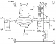
Maybe we can get both plates to idle at +8 or +9 volts ?
Just sayin' (+12V) - pVGS is probably > (GND) + nVGS
M1 is low pass shunt that adjusts for the desired plate
current, hopefully correcting for both grid leak currents.
Tail resistor wants to be a little smaller than otherwise
to cover the expected variation of grid leaks together
with the shunt action of M1...
Then you got 4.7x Schaded voltage gain at M2 assures
the plate voltage won't need to swing more than +/-2.5V
Reduced plate swing might help with the grid leak too.
VGS multiplier action is fixing filament voltage till the
main feedback loop gets warm enough to take over.
Might want to tweak R10 depending the actual VGS...
R13 is stiffening the tail with a positive feedback <1.
It would be sure disaster if R13 / R14 was > R6 / R5
Definitely don't want a resistor bigger than 22 here.
18 Ohms was merely the next lower standard value.
A CCS here could be even stiffer without any threat
of positive feedback. But its a few more parts, and
wouldn't be ever really be "constant" or "stiff" on
account of the leaks. Worth it? Maybe, maybe not...
R8 par R7 probably wants to be same like R6 par R5,
else the grid leaks may create different gird voltages.
Not built, not tested, not even simm'd. Just noodling...
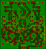
Attachments
Last edited:
- Status
- This old topic is closed. If you want to reopen this topic, contact a moderator using the "Report Post" button.