An update, I heard back from the Forum admins here and they say that the Vendors Bazaar would be the best spot for follow-on discussion of the 6 extra boards. I'll start a thread over there. I'll post the 4-layer Gerbers here when I have that design worked out.
I forgot to say that Seeed Studio has a small batch service for 50 - 300 quantity. At 50 pieces the price of a 4 layer board drops to just $3.50 or so, including shipping! Pretty amazing. I'll bet OSH Park's prices on quantity are similar.
I forgot to say that Seeed Studio has a small batch service for 50 - 300 quantity. At 50 pieces the price of a 4 layer board drops to just $3.50 or so, including shipping! Pretty amazing. I'll bet OSH Park's prices on quantity are similar.
Last edited:
mrsavage - will do, I'll put you on the list for 4. ") I might finish the layout on that massively parallel LME49990 amp and fab it too. I'm just really curious how it would sound given those ridiculously low distortion numbers from the datasheet for the LME49990 chips.
I might finish the layout on that massively parallel LME49990 amp and fab it too. I'm just really curious how it would sound given those ridiculously low distortion numbers from the datasheet for the LME49990 chips.
I'm going to go ahead and allow any number of boards per person until the extras are gone. These relatively low 4 layer prices really have me jazzed, so I may very well do another larger run later if all works out with these first 10. Given that I'll make 8 of the 10 available, rather than 6, and keep one extra along with the test board I'm going to build up.
I've started a thread in the Vendor's Bazaar forum and I will post all subsequent status updates about the extra boards there:
http://www.diyaudio.com/forums/vend...llel-njm4556al-two-stage-amp.html#post3517986
Also a correction on the small batch pricing I posted above. That was for 2 layer, and it is at iTead Studio. For 4 layer 8cm x16cm is around $7 per board with shipping. Still, pretty darn good for 4 layer.
I might finish the layout on that massively parallel LME49990 amp and fab it too. I'm just really curious how it would sound given those ridiculously low distortion numbers from the datasheet for the LME49990 chips. I'm going to go ahead and allow any number of boards per person until the extras are gone. These relatively low 4 layer prices really have me jazzed, so I may very well do another larger run later if all works out with these first 10. Given that I'll make 8 of the 10 available, rather than 6, and keep one extra along with the test board I'm going to build up.
I've started a thread in the Vendor's Bazaar forum and I will post all subsequent status updates about the extra boards there:
http://www.diyaudio.com/forums/vend...llel-njm4556al-two-stage-amp.html#post3517986
Also a correction on the small batch pricing I posted above. That was for 2 layer, and it is at iTead Studio. For 4 layer 8cm x16cm is around $7 per board with shipping. Still, pretty darn good for 4 layer.
Last edited:
Please add a second ODA pcb to my order if there are any left.
Thanks Tony
Added.
so you arent going to prototype before offering for sale? I think thats unwise, especially for the massively parallel 49990 amp, which I think could be an oscillation risk. if I were you, I would also provide for some sort of BGA or similar heatsink for the 49990, they get rather toasty and with them in such close proximity ...
Hey qusp! You are right, this one wound up a bit backwards. I prototyped the two layer version with the posted Gerbers, except for a couple of minor changes. This one is just adding two more layers with ground plane and some more routing. These 10 boards are the proto of the 4 layer. That is why I've giving everyone the option of cancelling at any time - if I discover a major bug after I build one up I'll need to do another run of 10 before shipping anything, which will add a couple of more weeks. No $$ collected until anything ships.
If I do a board for that parallel LME49990 amp I will do that one the other way around and proto/test it first. I 100% agree on the need for heat sinking all those chips! Was thinking about that. Tell me more about your idea - a ball grid array heatsink for use with the VQFN LME49990 package? There might be a clever way to heat sink the SOIC version by putting the chips on the bottom of the board. That amp would use the same B2-080 case the O2 amp uses. There is about that much space (height of the SMD chip) between the bottom of the PC board and the aluminum case bottom. Then it would come down to how to close the small remaining thermal gap. I'll have to do some measuring.
You are right, this one wound up a bit backwards. I prototyped the two layer version with the posted Gerbers, except for a couple of minor changes. This one is just adding two more layers with ground plane and some more routing. These 10 boards are the proto of the 4 layer. That is why I've giving everyone the option of cancelling at any time - if I discover a major bug after I build one up I'll need to do another run of 10 before shipping anything, which will add a couple of more weeks. No $$ collected until anything ships.If I do a board for that parallel LME49990 amp I will do that one the other way around and proto/test it first. I 100% agree on the need for heat sinking all those chips! Was thinking about that. Tell me more about your idea - a ball grid array heatsink for use with the VQFN LME49990 package? There might be a clever way to heat sink the SOIC version by putting the chips on the bottom of the board. That amp would use the same B2-080 case the O2 amp uses. There is about that much space (height of the SMD chip) between the bottom of the PC board and the aluminum case bottom. Then it would come down to how to close the small remaining thermal gap. I'll have to do some measuring.
Last edited:
hey mate!, I love how you always take my critique in the spirit its intended instead of getting all riled up like some of the more..erm.. philosophical members do. sounds like a decent plan to me, I didnt catch all those details, my apologies.
yep, something like these from Enzotech, the HCA series, preferrably with clip. especially now that itead (or is it seed) are offering slot cutting free as part of the standard cost.
Yes you could also put the 49990 on the bottom, add a bunch of thermal vias to a clear solid copper area on the top, use some sekisui thermal tape or silver epoxy to provide low thermal impedance to the heatsink. I love the copper ones for extra bling factor too or you could go really mad and get one of their spread pin ones. I like the HCA though, as its nice and low profile. this will also help them act as one device with thermal coupling. the 37.5 x 37.5 x 6mm one should be a nice size.
btw yes, loving the itead and seeed options now, cheap 4 layer with cheap shipping, i've got some boards running with them next week as well as some flex PCB interconnects for power, input and output 'wiring' now if they up the ante to 6 layer and increase possible copper weight, i'll be in heaven.
yep, something like these from Enzotech, the HCA series, preferrably with clip. especially now that itead (or is it seed) are offering slot cutting free as part of the standard cost.
Yes you could also put the 49990 on the bottom, add a bunch of thermal vias to a clear solid copper area on the top, use some sekisui thermal tape or silver epoxy to provide low thermal impedance to the heatsink. I love the copper ones for extra bling factor too
or you could go really mad and get one of their spread pin ones. I like the HCA though, as its nice and low profile. this will also help them act as one device with thermal coupling. the 37.5 x 37.5 x 6mm one should be a nice size.btw yes, loving the itead and seeed options now, cheap 4 layer with cheap shipping, i've got some boards running with them next week as well as some flex PCB interconnects for power, input and output 'wiring' now if they up the ante to 6 layer and increase possible copper weight, i'll be in heaven.
Heat Sink for the Massively Parallel Headphone AMP
In the Electronic Products Magazine (June 2013), I came across a heat sink aid
from CTS Corporation - EC, Sensors & Actuators, EMS!. It's about there low-profile thin-fin heat sinks that have
heights from 6.3mm to 32.6mm. They require no special tools to assemble on the
IC packages or any additional holes on the PCB. They suit large IC's or a
large number of IC's with heat dissipation needs. The BDN extruded heat sinks
have a pre-applied adhesive tape that peels off and sticks onto the component(s).
The adhesive shear strength at 100C is 36psi or so, hence, a one-inch square
heat sink would require a 36-lib force to remove. Take a look. They look like they
would work for the output driver chips. Take care.
mrsavage - hey I like that part you found! The LME49990 chip array on that amp measures about 40mm x 25mm on the layout, which is 1.6 inch x 0.98. The 1.6 x 1.6 heatsink might be the best, then just slice one side off at 0.98. Digikey has them:
BDN16-3CB/A01 CTS Thermal Management Products | 294-1103-ND | DigiKey (Digikey 294-1103-ND)
Or use two of the 0.91 x 0.91 sinks and cut one down slightly to make 1.6inch.
BDN09-3CB/A01 CTS Thermal Management Products | 294-1097-ND | DigiKey (Digikey 294-1097-ND)
The thermal adhesive tape on the sink solves another problem. The top of all those chips won't be exactly plane level of course and would leave tiny gaps if just in contact with a metal surface. The thermal adhesive tape would also act as a gap filler.
qusp - sorry about the delayed reply, I've haven't had a chance to look at the forum for a few days. I didn't know that those fab houses offered slot cutting! wowwww. Now that opens up a few possibilities. The vertical RCA jacks have rectangular plastic mounting tabs on each side that actually specify slots in the PCB footprint. I used holes since I didn't think I could do slotting. I'll have to go back and change that.
Although chips on the bottom seems like kind of an elegant solution, I think practically it would probably fail. The top and bottom of the aluminum case "warp" ever so slightly in the middle, making for a tricky thermal bond. Then there is the issue of sliding the board in. Silicon pad material (like those silicon TO-220 pads) would probably have a tacky surface that would bunch up under a sliding motion.
Those adhesive heatsinks mrsavage found sound like a good way to go. It also gets things turned around in the right direction - up - for convection. Even with a good thermal bond to the case I would probably worry that I was essentially creating an enclosed oven with the chips on the bottom.
Well in some 4-layer news, I've already come up with one slick change that makes use of the extra routing layer. I'm modifying the relay circuit to do away with the separate 24V regulator chip and instead just tap into the +/-18.5Vdc from the LM pre-regulator chips. The relay is then changed to the 48V coil unit of the same G6A Omron series. The relay has a "must operate" voltage of 70% of the rated coil voltage, so 18.5Vdc x 2 = 37Vdc should work. I wanted to do that originally, but without the extra routing layer there was no way to get the connections back to the pre-regulators made, at least without more jumper wires.
But the win isn't just getting rid of the regulator chip. The new arrangement will prevent the headphone relay from operating if someone accidentally plugs in a DC adapter rather than AC. That would "light up" only one rail, with a resulting rail-to-rail voltage a few volts less than the 48V relay's minimum pull-in voltage on Omron's datasheet graph. I've always thought that these dual rail half wave supplies need that particular protection.
So the change adds "accidental DC power adapter" protection to the relay circuit, while keeping the existing turn-on anti-thump delay and accelerated break at turn-off.
BDN16-3CB/A01 CTS Thermal Management Products | 294-1103-ND | DigiKey (Digikey 294-1103-ND)
Or use two of the 0.91 x 0.91 sinks and cut one down slightly to make 1.6inch.
BDN09-3CB/A01 CTS Thermal Management Products | 294-1097-ND | DigiKey (Digikey 294-1097-ND)
The thermal adhesive tape on the sink solves another problem. The top of all those chips won't be exactly plane level of course and would leave tiny gaps if just in contact with a metal surface. The thermal adhesive tape would also act as a gap filler.
qusp - sorry about the delayed reply, I've haven't had a chance to look at the forum for a few days. I didn't know that those fab houses offered slot cutting! wowwww.
Now that opens up a few possibilities. The vertical RCA jacks have rectangular plastic mounting tabs on each side that actually specify slots in the PCB footprint. I used holes since I didn't think I could do slotting. I'll have to go back and change that. Although chips on the bottom seems like kind of an elegant solution, I think practically it would probably fail. The top and bottom of the aluminum case "warp" ever so slightly in the middle, making for a tricky thermal bond. Then there is the issue of sliding the board in. Silicon pad material (like those silicon TO-220 pads) would probably have a tacky surface that would bunch up under a sliding motion.
Those adhesive heatsinks mrsavage found sound like a good way to go. It also gets things turned around in the right direction - up - for convection. Even with a good thermal bond to the case I would probably worry that I was essentially creating an enclosed oven with the chips on the bottom.
Well in some 4-layer news, I've already come up with one slick change that makes use of the extra routing layer. I'm modifying the relay circuit to do away with the separate 24V regulator chip and instead just tap into the +/-18.5Vdc from the LM pre-regulator chips. The relay is then changed to the 48V coil unit of the same G6A Omron series. The relay has a "must operate" voltage of 70% of the rated coil voltage, so 18.5Vdc x 2 = 37Vdc should work. I wanted to do that originally, but without the extra routing layer there was no way to get the connections back to the pre-regulators made, at least without more jumper wires.
But the win isn't just getting rid of the regulator chip. The new arrangement will prevent the headphone relay from operating if someone accidentally plugs in a DC adapter rather than AC. That would "light up" only one rail, with a resulting rail-to-rail voltage a few volts less than the 48V relay's minimum pull-in voltage on Omron's datasheet graph. I've always thought that these dual rail half wave supplies need that particular protection.
So the change adds "accidental DC power adapter" protection to the relay circuit, while keeping the existing turn-on anti-thump delay and accelerated break at turn-off.
Last edited:
you misunderstand, chips bottom, heatsink on top OF THE PCB. you will find the copper a better place to heatsink from if you do it right. much larger contact area
Ah, I see, hence the thermal vias. I did a design like that early on with this desktop amp, back when I was thinking about using 2 parallel LME49600s, one on top and one on the bottom for each channel. Yep, that would definitely work better than my idea of heatsinking to the case bottom.
Something interesting on the 4 layer stuff. I was just studying the information on Seeed's site and I see that the inner layers are thinner - 0.5oz as opposed to 1oz on top and bottom - so the inner traces need to be wider to handle the same current. Perfect for what I have in mind, just some additional signal routing and the ground plane. The spacings are also different. The outer-to-inner is thinner than outer to outer, which may or may not make a difference depending on what is being done with the circuit.
Last edited:
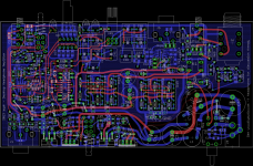
Well it doesn't look like 4 layer is going to be difficult at all. I've left a significant amount of space between the ground plane and the traces to reduce the fringing fields. I'm leaving the jumpers on power traces since they can be top soldered as well as bottom soldered to eliminate via current problems. Saves space over just punching through multiple vias. '
The plane under the input parts will be connected to the input (clean / high impedance and low current) segment of the ground star, while the plane under the output parts is connected to the output (dirty / low impedance and high current) segment of the ground star. No plane under the power supply parts and no connection to the power supply reference section of the ground star, since there is nothing to gain and only noise to introduce.
I've left a significant amount of space between the ground plane and the traces to reduce the fringing fields. I'm leaving the jumpers on power traces since they can be top soldered as well as bottom soldered to eliminate via current problems. Saves space over just punching through multiple vias. 'The plane under the input parts will be connected to the input (clean / high impedance and low current) segment of the ground star, while the plane under the output parts is connected to the output (dirty / low impedance and high current) segment of the ground star. No plane under the power supply parts and no connection to the power supply reference section of the ground star, since there is nothing to gain and only noise to introduce.
Attachments
Last edited:
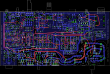
This one just went out to fab. 4 layer Gerbers below.
I double checked the whole layout and made a few updates. The gain switch and pot are now a bit farther forward. The 3.5mm input jack now has more spacing and the PCB holes for front external input (like an ODAC or front panel input jack) are back, as well as those existing on the rear RCA input connector. In other words, an ODAC can be wired into either the front holes near the 3.5mm connector or to those near the rear RCA connector.
If wired into the rear connector then the front 3.5mm jack still remains fully functional and switch-selectable with the front panel input select switch. That method would also make the ODAC output available at the rear RCA connectors, so they would effectively become an ODAC out (for pre-amps).
I'll post again once the boards are back and I have one built up and tested.
4 layer Gerbers below.I double checked the whole layout and made a few updates. The gain switch and pot are now a bit farther forward. The 3.5mm input jack now has more spacing and the PCB holes for front external input (like an ODAC or front panel input jack) are back, as well as those existing on the rear RCA input connector. In other words, an ODAC can be wired into either the front holes near the 3.5mm connector or to those near the rear RCA connector.
If wired into the rear connector then the front 3.5mm jack still remains fully functional and switch-selectable with the front panel input select switch. That method would also make the ODAC output available at the rear RCA connectors, so they would effectively become an ODAC out (for pre-amps).
I'll post again once the boards are back and I have one built up and tested.
Attachments
Last edited:
Here are a first pass at the front and back panels for this project using the Front Panel Express software. I'll also post all the hole locations and dimensions of the final result. Since all the holes are round a drill press would do the job just fine with the panels that come with the B4-080 box.
Scroll down on both-
Scroll down on both-
Attachments
Last edited:
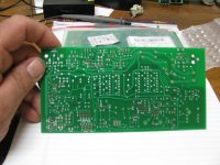
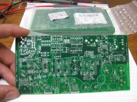
The boards for this project are back from fabrication already! Speedy. I have to say that I am extremely impressed with the results. Even nicer than the previous 2 layer boards I've had done. Super alignment, nice crisp printing, great surface finish. Maybe they spend more time on the pricer 4 layer boards, or maybe I just got luckier this time. The various 3rd layer traces ohm-check just fine.
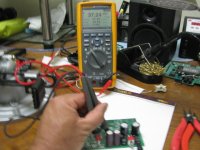
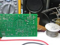
I'm going to build one up and see if it flies. So far so good... The voltage on the meter for the positive rail is the correct answer, of course, for unloaded voltage off the caps with the 24Vac transformer and 121Vac on the primary from the wall socket.
The various 3rd layer traces ohm-check just fine.I'm going to build one up and see if it flies. So far so good... The voltage on the meter for the positive rail is the correct answer, of course, for unloaded voltage off the caps with the 24Vac transformer and 121Vac on the primary from the wall socket.
Attachments
Last edited:
Erik - thanks!
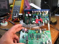
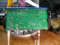
Well, it lives! In the photo below the new 4 layer board is in the vise at the top, with the old 2 layer board below (partially scavenged of parts). Sounds fantastic. I've been listening to a bunch of old Simon and Garfunkel songs with the new amp for the last hour or so. Almost fully built up. I can't find one of the 4.7uF caps, I need to order in LEDs or zeners for the clipping circuit reference (may try zeners this time) and need to solder in the pre-amp parts.
I'm want to do a bunch of measurements on it now, which I'll post. I want to look at full load power supply ripple on the scope and frequency response for a few waveshapes across the output load range.
The power rails were right on the nose with the meter. +7.023Vdc/-7.004Vdc and +16.092Vdc/-15.936Vdc. The output DC offset is +1.447Vdc on one channel and -1.630Vdc on the other, with the 0.5R output balancing resistors in now. The new headphone output relay circuit across the pre-regulators is also right on the mark. Exactly 6 seconds of delay, as before with the previous +24Vdc circuit.
There are no major screw ups with the 4 layer PCB! At least none I've found yet. I've also learned from another forum of an alternative place (to Front Panel Express) that has a 40% off sale, which would work out to be about half the cost of FPE. I think I'm going to test that (and my measurements) out and get the panels fabbed.
I'm still just flabergasted at the complete lack of *any* background hiss on this thing, even with the volume control fully up on the high gain setting. And that is using my uber sensitive AKG K550's. Every now and then something actually works out better than expected. During a full volume test at the highest gain setting this evening I thought that I was finally hearing just the faintest traces of hiss, right at the edge of hearing. Then I remembered that the input cable was still plugged into the laptop, which was on mute. Pulled the cable out, which grounds the inputs via the jack, and back to zero backgrouund hiss. That was the amplified hiss of the muted laptop output stage (the source) I was hearing, not the amp's internals.
Well, it lives!
In the photo below the new 4 layer board is in the vise at the top, with the old 2 layer board below (partially scavenged of parts). Sounds fantastic. I've been listening to a bunch of old Simon and Garfunkel songs with the new amp for the last hour or so. Almost fully built up. I can't find one of the 4.7uF caps, I need to order in LEDs or zeners for the clipping circuit reference (may try zeners this time) and need to solder in the pre-amp parts.I'm want to do a bunch of measurements on it now, which I'll post. I want to look at full load power supply ripple on the scope and frequency response for a few waveshapes across the output load range.
The power rails were right on the nose with the meter. +7.023Vdc/-7.004Vdc and +16.092Vdc/-15.936Vdc. The output DC offset is +1.447Vdc on one channel and -1.630Vdc on the other, with the 0.5R output balancing resistors in now. The new headphone output relay circuit across the pre-regulators is also right on the mark. Exactly 6 seconds of delay, as before with the previous +24Vdc circuit.
There are no major screw ups with the 4 layer PCB! At least none I've found yet. I've also learned from another forum of an alternative place (to Front Panel Express) that has a 40% off sale, which would work out to be about half the cost of FPE. I think I'm going to test that (and my measurements) out and get the panels fabbed.
I'm still just flabergasted at the complete lack of *any* background hiss on this thing, even with the volume control fully up on the high gain setting. And that is using my uber sensitive AKG K550's. Every now and then something actually works out better than expected.
During a full volume test at the highest gain setting this evening I thought that I was finally hearing just the faintest traces of hiss, right at the edge of hearing. Then I remembered that the input cable was still plugged into the laptop, which was on mute. Pulled the cable out, which grounds the inputs via the jack, and back to zero backgrouund hiss. That was the amplified hiss of the muted laptop output stage (the source) I was hearing, not the amp's internals.Attachments
Last edited:
Interested in a PCB of the final version and front panel etc... heck make it a kit
+1
agdr, what is the other site for front panels? I need some made for an O2 for a friend.
Thanks
-Erik
- Home
- Amplifiers
- Headphone Systems
- A version of an O2 Desktop Amp (ODA)