Here are the Gerbers, BOM and build instructions
I have the OPA2188 in now for the servo. So here are the Gerbers, BOM, and build instructions. I eventually came to realize that if I post .zip and .pdf files here on DIYA they will be downloadable, so no need for Google Docs.
If anyone builds it, please post the results!")
Have fun,
-agdr
I have the OPA2188 in now for the servo. So here are the Gerbers, BOM, and build instructions. I eventually came to realize that if I post .zip and .pdf files here on DIYA they will be downloadable, so no need for Google Docs.
If anyone builds it, please post the results!
Have fun,
-agdr
Attachments
Last edited:
I have the OPA2188 in now for the servo. So here are the Gerbers, BOM, and build instructions. I eventually came to realize that if I post .zip and .pdf files here on DIYA they will be downloadable, so no need for Google Docs.
If anyone builds it, please post the results!
Have fun,
-agdr
So, our trusted specialists - who will the first to deliver a kit?
Count me in for 2 complete ones!
Brgds
You may want to wait a week or two - there is probably going to be a V 1.1. The files posted above work but I've thought up a few minor upgrades already.
I forgot to say that as of yet I haven't come up with a way to properly distortion-test it, so the "objective desktop amp" here isn't really objective yet. Looks like leasing an Audio Precision is about $2,000 a month that I would rather spend on a ghz scope and some other toys. I'm not going to even bother with RMAA.
But at least the design is RocketScientist's with a lower (rated) distortion set of gain chips, lower Johnson noise pot arrangement, what should be lower output stage distortion by paralleling more output chips, and lower DC output offset from the smaller input resistor and DC servo if that is used. So unless I've seriously mucked something up with the layout (always possible!) the distortion and noise *should* be slightly better than the O2. At least the potential is there. The properly measured distortion and noise floor result would certainly be interesting.
The ODA is essentially an "O2 headphone amp on steriods". More voltage swing, more output current capability, more gain switch choices, more input & output jack types, clipping indicator, attenuation, lower noise pot, better voltage regulators, DC servo, no-thump relay, etc....
The files posted above work but I've thought up a few minor upgrades already.I forgot to say that as of yet I haven't come up with a way to properly distortion-test it, so the "objective desktop amp" here isn't really objective yet. Looks like leasing an Audio Precision is about $2,000 a month that I would rather spend on a ghz scope and some other toys. I'm not going to even bother with RMAA.
But at least the design is RocketScientist's with a lower (rated) distortion set of gain chips, lower Johnson noise pot arrangement, what should be lower output stage distortion by paralleling more output chips, and lower DC output offset from the smaller input resistor and DC servo if that is used. So unless I've seriously mucked something up with the layout (always possible!) the distortion and noise *should* be slightly better than the O2. At least the potential is there. The properly measured distortion and noise floor result would certainly be interesting.
The ODA is essentially an "O2 headphone amp on steriods".
More voltage swing, more output current capability, more gain switch choices, more input & output jack types, clipping indicator, attenuation, lower noise pot, better voltage regulators, DC servo, no-thump relay, etc....
Last edited:
It is possible to make rather good measurements using mediocre spectrum analyzer or sound card. You just need to use some way of suppression of main harmonic (nulling, notch filtering, etc) plus preamplifier (optional). This way you sort of artificially extend (or more accurate "shift") dynamic range of measurement setup towards low end. For example notch filter plus 20-30dB preamp and a sound card may be enough to see distortion on the level of -130..140dB.
availlyrics - doing my best to remove my obvious bias (!) I really can't hear any difference at all, better or worse, A/B'ing my O2s vs. the ODA, except for background noise and (measured) DC offset. Now that is with my AKG K550s and Shure SRH940s though, neither of which even remotely loads the ODA either with voltage swing or current draw. Where the ODA would really come into its own vs. the O2 would be with cans that need the extra voltage swing, extra current capability, or for situations that need the extra gain settings or input/output jacks.
The ODA wins on quiet background and it isn't even subtle, enough of a difference to eliminate listening bias. I can clearly hear a very tiny amount of background hiss on the O2's with both of my headphones when the gain is all the way up to 6.5x and inputs grounded. No such hiss on the ODA, even when I changed resistors and bumped one channel up to 12x.
The lower background noise in the ODA has to be some combination of the lower-noise gain stage LME49990 and the new 1K pot + 4.99kK output stage bias resistor higher-current arrangement. Those are the only two pieces different from the O2 that could have a difference on background noise. Theoretically the paralleled op amps help too, but only at higher volume. Turns out the noise of the paralleled op amps adds by root mean square (RMS) while signal adds linearly, giving a lower signal-to-noise ratio. But the absolute value of the noise is not less, just the ratio, so that shouldn't improve anything at small signal (no signal) levels.
And the other "win" is the DC offset, which I measure at 1mV static and down to a couple of hundred microvolts with music. That should get even lower when the servo is hooked in. BTW, I have not yet tested that servo circuit but still plan to. I have a few OPA2188's on order from mouser. Going to solder them on an adapter board and wire them into the existing PCB. My view on electronics design is "if it isn't tested and verified then it doesn't work".
As for the dScope measurement, by all means if someone out there has a recent model dScope or AP and would be willing to test it and post the results (RocketScientist, are you still out there? ), send me a PM and I'll pay for the shipping in both directions. Only request is tell it like it really is, whether it turns out to be good or horrible, no bias just the facts. If the results are on the horrible side then its back to the drawing board to find out why and make the necessary changes.
Sergey888 - now there is a project I would love to see someone post! A PCB that would make RMAA somewhat believable. A low noise input pre-amplifier, a specification for one specific sound card model, and an output filter(s) to filter out the native sound card junk, like you say. Plus address some of the other RMAA failings vs. a real tester that RocketScientist / NwAvGuy detailed in one of his blog posts here:
NwAvGuy: RightMark Audio Analyzer
Then verify the results vs. a recent model Audio Precision or dScope. I'll bet a PCB like that would be extremely popular. I would buy one. You should design one! I've seen an old post somewhere for a RMAA pre-amp PC board. I think it may have been on the old Headwize website, but I can't find a link at the moment.
In fact, if someone were designing a PC board for this, it may be best to do away with the sound card altogether and include the sound card components on the new PC board where everything is specified. So the RMAA software could still run on a PC, but ALL the parts, including "soundcard" parts are on the new PC board with the PC just talking to it via a USB connection. Effectively the new board would *be* a low-end little dScope or Audio Precision, controlled by the RMAA user interface software on the PC. Or something like that.
The ODA wins on quiet background and it isn't even subtle, enough of a difference to eliminate listening bias. I can clearly hear a very tiny amount of background hiss on the O2's with both of my headphones when the gain is all the way up to 6.5x and inputs grounded. No such hiss on the ODA, even when I changed resistors and bumped one channel up to 12x.
The lower background noise in the ODA has to be some combination of the lower-noise gain stage LME49990 and the new 1K pot + 4.99kK output stage bias resistor higher-current arrangement. Those are the only two pieces different from the O2 that could have a difference on background noise. Theoretically the paralleled op amps help too, but only at higher volume. Turns out the noise of the paralleled op amps adds by root mean square (RMS) while signal adds linearly, giving a lower signal-to-noise ratio. But the absolute value of the noise is not less, just the ratio, so that shouldn't improve anything at small signal (no signal) levels.
And the other "win" is the DC offset, which I measure at 1mV static and down to a couple of hundred microvolts with music. That should get even lower when the servo is hooked in. BTW, I have not yet tested that servo circuit but still plan to. I have a few OPA2188's on order from mouser. Going to solder them on an adapter board and wire them into the existing PCB. My view on electronics design is "if it isn't tested and verified then it doesn't work".
As for the dScope measurement, by all means if someone out there has a recent model dScope or AP and would be willing to test it and post the results (RocketScientist, are you still out there?
), send me a PM and I'll pay for the shipping in both directions. Only request is tell it like it really is, whether it turns out to be good or horrible, no bias just the facts. If the results are on the horrible side then its back to the drawing board to find out why and make the necessary changes.Sergey888 - now there is a project I would love to see someone post! A PCB that would make RMAA somewhat believable. A low noise input pre-amplifier, a specification for one specific sound card model, and an output filter(s) to filter out the native sound card junk, like you say. Plus address some of the other RMAA failings vs. a real tester that RocketScientist / NwAvGuy detailed in one of his blog posts here:
NwAvGuy: RightMark Audio Analyzer
Then verify the results vs. a recent model Audio Precision or dScope. I'll bet a PCB like that would be extremely popular. I would buy one. You should design one!
I've seen an old post somewhere for a RMAA pre-amp PC board. I think it may have been on the old Headwize website, but I can't find a link at the moment.In fact, if someone were designing a PC board for this, it may be best to do away with the sound card altogether and include the sound card components on the new PC board where everything is specified. So the RMAA software could still run on a PC, but ALL the parts, including "soundcard" parts are on the new PC board with the PC just talking to it via a USB connection. Effectively the new board would *be* a low-end little dScope or Audio Precision, controlled by the RMAA user interface software on the PC. Or something like that.
Last edited:
agdr
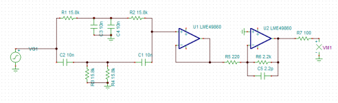
To make a notch filter with preamp you need less than you think. I assembled few myself using prototyping board. There is a schematic below shows simple notch filter with freq around 1kHz and Q of 0.5 and preamp with gain of 20dB. The only thing you need is tight tolerance components for the filter itself. In this case you may want to select manually matching component from a tray.
As for opamp in preamp, it is good to use some high performer/low noise, but it is not really essential. Signal level will be very low, so distortion of amplifier are going to be on a very low level. You can also deal with noise decreasing resolution bandwidth of a spectrum analyses. I was using LM4562 myself. Probably OPA211/1611 can give a bit better noise level. May be LME49990, but I think this is overkill. Resistors - thin film MELF 0204, capacitors - NP0 1206.
To achieve good main tone suppression you will need to tune freq of sig gen withing 1Hz. With these values I was usually getting something around 1013Hz and something like 70dB of suppression. Mind you that if you will be using sound cards you will notice that frequency is a bit off from card to card.
Do not forget that notch filter affects also level of harmonics, so you will need to add some correction coefficients to numbers you will be getting.
If you want to have higher Q, you may do as described in this paper http://www.analog.com/static/imported-files/tutorials/MT-225.pdf, but don't push it to far, will be hard to find the center of the notch.
Also depends on situation some DC decoupling and EMI filtering can make a difference
Attachments
Last edited:
... No such hiss on the ODA, even when I changed resistors and bumped one channel up to 12x.
The lower background noise in the ODA has to be some combination of the lower-noise gain stage LME49990 and the new 1K pot + 4.99kK output stage bias resistor higher-current arrangement.....
You had already won half of the battle with the choice of "LME49990 and the new 1K pot + 4.99k" combination
agdr
I just realised that it could make sence to use JFET input op amp, at least for the fist stage. With BJT input current noise will dominate over the thermal noise of the filter itself.
"FET or Bipolar – You can broadly divide audio op amps into these two categories based on the type of transistors used in their input stage—FET or bipolar. Some claim various types of FET (JFET, Bi-FET, Di-FET, etc.) inputs “sound better” but they’re usually more noisy in real world use. The main reason to use FET inputs is for their superior DC performance (especially bias current) which is mostly useless in an audio application. The one exception being, if you’re going to hang a volume control right off the input, a FET op amp will generally put less DC through the volume control wiper. This helps reduce the “rustling” noise you get when you adjust the volume. It also can allow larger resistor values without excessive DC offset. But the O2 solves these issues in other ways so FETs are generally more of a liability if accuracy is the goal. The ultra high-end FET devices, like the Di-Fet OPA627, are an exception to the rule but the FET OPA2134 is not. It performs worse in some ways than the much cheaper bipolar 5532"
from NwAvGuy: Op Amp Measurements
On the FETs - the way the ODA gain stage has wound up is with one LME49990 per channel. But as luck would have it the OPA627 and OPA827 (FET input) have exactly the same pin-out and are available in the same SOIC8 package. So if someone wants to experiment, just solder in a couple of OPA627s or OPA827s instead of the LME49990s and give it a try. Don't use the OPA637 though since it isn't unity gain stable or noise gain stable. Would have to be the OPA627 or OPA827.
Well I just managed to get the clipping indicator on the ODA board working. I have to say this indicator absolutely rocks. Every O2 needs one of these. Wasn't working until now because (1) I forgot to solder in the resistor that is in series with the clipping indicator LED and (2) pin 1 of the TL064 didn't get soldered properly.
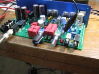
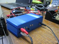
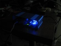
The first two photos below show the results. The two green LEDs are the power LEDs, one per rail, and the red LED to the right is the clipping indicator. I had the source input level and gain set so that it was flashing on and off intermittently with the clipping, like it should, and took a few photos to catch it while "on" like this.
I have the DMM in the background set to record AC peaks, and on the screen you can see the highest peak is 4.6V. Remember that the clipping indicator is on the FIRST stage, the output of the gain stage, so the meter is hooked to that black test clip that is taking the signal off the input to one attenuation resistor, which is the output of one channel's LME49990 chip. The position of the pot won't matter for clipping, of course, since it is what the gain stage is powering. But the gain switch position does matter. Here I have it set to the 3rd rotary position (4x before the atten resistor). Setting the gain switch to the last 6x position results in the clipping LED going on solid (continuous) red, as it should.
I have the power rails set for the lower +/-7Vdc position. I've measured the two blue LEDs that form the window comparator upper and lower reference voltage levels at 2.9V for one and 2.8V for the other. That gives clipping reference levels of 7Vdc - 2.9Vdc = 4.1Vdc and -7Vdc - (-2.8Vdc) = -4.2Vdc.
So you can see the meter's peak gain stage measurement of 4.6V is right where it should be with clipping reference levels (the levels that have to be exceeded to signal clipping) of 4.1V in the positive swing direction and -4.2V in the negative directly. By dropping the volume level of the source (laptop) very slowly and carefully I was able to get the music peaks right at 4.1 and could see the LED just barely start to flash. The source level worked out well. On the 4x gain setting clipping happens with the PC volume slider up about 95% of the way. The PC software volume slider is very logarithmic, so a little movement produces a big output change near the top.
Note that actual clipping isn't being measured, just how close the gain stage output swing is getting to the rail. But by the time the swing is within 3V like this for +/-7V rails, it is getting near to the maximum swing level for the chips. The main purpose is to alert the user that the swing is getting too large and any distorted sounding music that follows is due to clipping, not the amp. With the O2 there is no way to know how close you are getting to clipping without a scope or knowing exaclty what the output of your source is, peak, times the O2 gain.
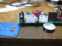
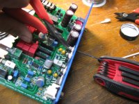
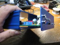
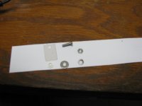
The other pictures below show adding the back panel and attaching the heat-sink mica washers and hardware to the voltage regulators. I used 3mm x 10mm stainless steel button head bolts, fender washers, lock washers, nuts, etc. I made the panel myself using caliper measurements and a step drill. I'm working on a CAD pattern for Front Panel Express from the PCB and part's CAD measurements. Should look more professional than my panel here.
The rear panel RCA jacks and input selector switch work! That is what I used for the tests above.
I've uncovered a problem with the layout and schematic I posted. When I switched from using a 16Vac transformer to 24Vac I discovered that the protection diodes across the pre-regulators, D3 and D4, are backwards! That is right, they were completely bypassing the pre-regulators, Just flip them around. I'm 500% more impressed with Linear Technology parts now, though. With the pre-regulators bypassed the LT1963A, with a maximum datasheet input voltage of 20V, got hit with 35V and survived. I couldn't believe it. I've had parts actually explode when hit with just a couple of volts past maximum. It did shut down with the overload, but then came right back with proper voltage applied. The LT3015 kept regulating right on the money even with 35V going into the 30v max part. I've replaced both LT regulators regardless, figuring they were long-term damaged, but still a pretty impressive showing for those LT parts.
Don't use the OPA637 though since it isn't unity gain stable or noise gain stable. Would have to be the OPA627 or OPA827.Well I just managed to get the clipping indicator on the ODA board working. I have to say this indicator absolutely rocks.
Every O2 needs one of these. Wasn't working until now because (1) I forgot to solder in the resistor that is in series with the clipping indicator LED and (2) pin 1 of the TL064 didn't get soldered properly.The first two photos below show the results. The two green LEDs are the power LEDs, one per rail, and the red LED to the right is the clipping indicator. I had the source input level and gain set so that it was flashing on and off intermittently with the clipping, like it should, and took a few photos to catch it while "on" like this.
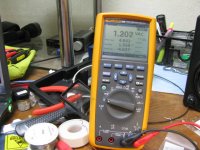
I have the DMM in the background set to record AC peaks, and on the screen you can see the highest peak is 4.6V. Remember that the clipping indicator is on the FIRST stage, the output of the gain stage, so the meter is hooked to that black test clip that is taking the signal off the input to one attenuation resistor, which is the output of one channel's LME49990 chip. The position of the pot won't matter for clipping, of course, since it is what the gain stage is powering. But the gain switch position does matter. Here I have it set to the 3rd rotary position (4x before the atten resistor). Setting the gain switch to the last 6x position results in the clipping LED going on solid (continuous) red, as it should.
I have the power rails set for the lower +/-7Vdc position. I've measured the two blue LEDs that form the window comparator upper and lower reference voltage levels at 2.9V for one and 2.8V for the other. That gives clipping reference levels of 7Vdc - 2.9Vdc = 4.1Vdc and -7Vdc - (-2.8Vdc) = -4.2Vdc.
So you can see the meter's peak gain stage measurement of 4.6V is right where it should be with clipping reference levels (the levels that have to be exceeded to signal clipping) of 4.1V in the positive swing direction and -4.2V in the negative directly. By dropping the volume level of the source (laptop) very slowly and carefully I was able to get the music peaks right at 4.1 and could see the LED just barely start to flash. The source level worked out well. On the 4x gain setting clipping happens with the PC volume slider up about 95% of the way. The PC software volume slider is very logarithmic, so a little movement produces a big output change near the top.
Note that actual clipping isn't being measured, just how close the gain stage output swing is getting to the rail. But by the time the swing is within 3V like this for +/-7V rails, it is getting near to the maximum swing level for the chips. The main purpose is to alert the user that the swing is getting too large and any distorted sounding music that follows is due to clipping, not the amp. With the O2 there is no way to know how close you are getting to clipping without a scope or knowing exaclty what the output of your source is, peak, times the O2 gain.
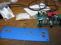
The other pictures below show adding the back panel and attaching the heat-sink mica washers and hardware to the voltage regulators. I used 3mm x 10mm stainless steel button head bolts, fender washers, lock washers, nuts, etc. I made the panel myself using caliper measurements and a step drill. I'm working on a CAD pattern for Front Panel Express from the PCB and part's CAD measurements. Should look more professional than my panel here.
The rear panel RCA jacks and input selector switch work! That is what I used for the tests above.
I've uncovered a problem with the layout and schematic I posted. When I switched from using a 16Vac transformer to 24Vac I discovered that the protection diodes across the pre-regulators, D3 and D4, are backwards! That is right, they were completely bypassing the pre-regulators, Just flip them around. I'm 500% more impressed with Linear Technology parts now, though. With the pre-regulators bypassed the LT1963A, with a maximum datasheet input voltage of 20V, got hit with 35V and survived. I couldn't believe it. I've had parts actually explode when hit with just a couple of volts past maximum. It did shut down with the overload, but then came right back with proper voltage applied. The LT3015 kept regulating right on the money even with 35V going into the 30v max part. I've replaced both LT regulators regardless, figuring they were long-term damaged, but still a pretty impressive showing for those LT parts.
Attachments
-
 IMG_1893.JPG202.8 KB · Views: 324
 -
 IMG_1892.JPG180.8 KB · Views: 335
 -
 IMG_1872.JPG198.8 KB · Views: 322
 -
 IMG_1875.JPG179.5 KB · Views: 302
 -
 IMG_1876.JPG221 KB · Views: 309
 -
 IMG_1879.JPG176.5 KB · Views: 154
 -
 IMG_1890.JPG205.8 KB · Views: 145
 -
 IMG_1882.JPG103.4 KB · Views: 125
 -
 IMG_1889.JPG86.5 KB · Views: 114
Last edited:
availlyrics
Didn't expect this...
JFET input has much lower input current noise, in range of fA instead of pA for BJT. This matters when it works from high impedance source. If current noise multiplied by impedance of the source higher than voltage noise or/and thermal noise - it will dominate. In example I've shown voltage noise of the notch filter will be around ten of nV/sqrtHz, so input voltage noise of almost any low noise opamp will be less than that. But if you multiply typical input current noise of, for example NE5532, 2.7pA/sqrtHz by impedance, say 10k (freq dependent) you will get value around 27nV/sqrtHz. This noise source will dominate in this case. If you aiming for lower noise, you'll need opamp with lower input current noise. That is where JFET may have benefit, since they have lower input current noise.
Another way to improve situation with noise in this case is to drop all resistor values, for example 10 time, and increase all capacitors by the same factor. Despite thermal noise will go down only around 3.2 times, effect of opamp current noise will be scaled down by the factor of 10. This will allow to use BJT input opamps without danger of degradation of noise performance. This may also improve linearity, since distortion caused by non-linearity of input current will be also scaled down.
Though it may cause other problem, since filter may load signal source too havy.
Cheers
Last edited:
ODA V1.1 updated Gerbers, layout, schematic, BOM
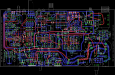
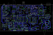
Here is V1.1 of the PC board Gerbers, layout, schematic, BOM and change list for this O2 Desktop Headphone Amp project.
I'll post a revised set of build instructions this weekend.
Front Panel Express CAD files for the front and back panels will come eventually... working on them.
Here is V1.1 of the PC board Gerbers, layout, schematic, BOM and change list for this O2 Desktop Headphone Amp project.
I'll post a revised set of build instructions this weekend.
Front Panel Express CAD files for the front and back panels will come eventually... working on them.
Attachments
-
ODA Gerbers V1.1 5_15_2013 agdr.zip215.6 KB · Views: 61
-
ODA V1.1 changes.pdf51.3 KB · Views: 77
-
 ODA layout low rez both layers.png176.2 KB · Views: 128
 -
ODA circuit.pdf838.6 KB · Views: 93
-
ODA layout both layers.pdf851.6 KB · Views: 84
-
ODA layout bottom layer.pdf793.3 KB · Views: 86
-
ODA V1.1 BOM 5_15_2013 agdr.pdf120 KB · Views: 74
-
 ODA layout bottom layer.png366.5 KB · Views: 114
 -
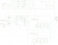 ODA circuit.jpg455.1 KB · Views: 121
Last edited:
@agdr
Is this http://www.diyaudio.com/forums/swap-meet/235381-audio-precision-system-one-gpib-pcmcia.html of any use to you?
The piece is so old that it reminded me of days when I had full hairs on my head
Is this http://www.diyaudio.com/forums/swap-meet/235381-audio-precision-system-one-gpib-pcmcia.html of any use to you?
The piece is so old that it reminded me of days when I had full hairs on my head
@Sergey888
Neither could I, especially when NwAvGuy had to come up with these reports after I ordered bunch of OPA2134 . I've not even opened the static bags.(Planning to build preamp for guitar in future) He also found FET opamps picking up stray 60Hz signal from the workbench area.
Neither could I, especially when NwAvGuy had to come up with these reports after I ordered bunch of OPA2134 . I've not even opened the static bags
.(Planning to build preamp for guitar in future) He also found FET opamps picking up stray 60Hz signal from the workbench area.@Sergey888
Neither could I.
I was a bit sarcastic there...
I respect NwAvGuy opinion, but personally don't care about those conclusions.
While input current noise effect may be not as much relevant for headphone amp, there are a lot of applications where it is highly important.
As I already mentioned, when opamp works from high impedance source, portion total system noise produced by input current noise may dominate, and in this situation you could get better noise performance using JFET input opamp, even if it has higher input voltage noise.
P.S. If circuit picks up some EMI from AC mains, very unlikely that the problem is in JFET input.
Last edited:
Congratulations
How does your amp performs against O2 in blind test with different h/p? BTW isn't there anybody on diyaudio who has AP /dsocpe who can help with the objective tests?
We have a dScope and I'll be glad to perform benchmarks.
First, I'd like agdr to clarify how this project complies with RocketScientist's no-derivatives license. As much as I'd like to design an ODA, we've explicitly avoided doing so in respect of NwAvGuy.
NwAvGuy said:THE LICENSE: Anyone is free to use the O2 design, as presented here, if they comply with the Creative Commons License. I don’t want any revenue from the O2 but I do humbly request everyone please respect the license which includes proper attribution. It’s good Karma. Also please note while the design is open (i.e. the files on Google Docs) the content on this blog is copyrighted and cannot be used without permission.The O2 is Open Source Hardware under a Creative Commons license. In addition to the language in the CC-BY-ND License, the O2 design is offered “as-is” with no warranty of any kind, either expressed or implied, including its suitability for anything you might want to use it for. You build and use it at your own risk. In plain English: If you can’t make the O2 work correctly, or as you had hoped, or damage your headphones, or your house burns down and your wife leaves you, you can’t blame me. Any similar DIY project has similar risks. For more, please see: Open Source Hardware
This work is licensed under a Creative Commons Attribution-NoDerivs 3.0 Unported License.
Specifically, the license states:
No Derivative Works — You may not alter, transform, or build upon this work.
Someone sent me this thread link a few hours ago and I've browsed through the bulk of the discussion. Forgive me if this has already been addressed.
NwAvGuy left everyone hanging with this CC BY-ND 3.0 license. He has exclusive authority to derive from his own work, meaning it's not really an open license. It's absolutely fine to experiment with a design for your own uses. Releasing a derivative work of a no-derivatives license is clearly against defined usage, sadly.
If the design differs substantially enough from O2, and does not share NwAvGuy's "Objective" title, I expect it's then permissible. Afterall, it can't be objective if it wasn't objectively designed under an audio analyzer.
Discuss?
Last edited:
First, I'd like agdr to clarify how this project complies with RocketScientist's no-derivatives license.
Hello John!
Good questions. My read of the license has always been no derivitives for commerical usage, but open source for DIY. All of the modifications I posted in the O2 mod thread here were based on that. RocketScientist himself even posted in that thread once or twice. This ODA project has always been purely DIY, not selling anything. I believe his intent of that no derivitives clause was specifically so that nobody would alter the O2 in a way to degrade the measured numbers, then go and sell it. But for home use, I've taken the license to mean go right ahead and wire the O2 up any way a person wants, as long as it is their personal unit, stays their unit, and does not get sold to others.
On the board and in the writings so far I'm stating that RocketScientist's original license applies to this ODA board as far as I'm concerned, with the intent that this ODA version could not be sold for money without RocketScientist's blessing either, just like the O2 amp.
Then the other problem is that he has disappeared. I used to exchange PMs and eamils with him, but not since he dissapeared last year. I've been contacted by one party along the way wanting to sell something O2 related who could not get hold of RocketScientist / NwAvGuy for a license release, and I had no luck in contacting him to pass that info along either. That one is a very good question for anyone out there familiar with actual GNU and Creative Commons case law. What happens with the license when the original party is no longer contactable for a release?
So I would agree with you, in terms of JDS or anybody else actually selling on ODA, that would probably be prohibited under the license terms, at least my read of it. I certainly understand if you would rather stay away from making any measurements on the ODA gizmo here.
Probably best done by a DIY'er rather than a company given, the license.The license issue would also make it dicey for any of the existing companies selling O2 parts to sell ODA boards, from my read of it. Given the license probably the most that could be done is a group buy of PC boards for DIY'ers. For that reason I've stayed away so far from contacting any of the O2 outfits about this ODA version so far. I was thinking about doing so originally but have since nixed the idea.
Last edited:
We have a dScope and I'll be glad to perform benchmarks....
Thanks for coming to rescue, I hope this GNU thing gets sorted out soon. Looking forward for dscope test results
Hello John!
Good questions. My read of the license has always been no derivitives for commerical usage, but open source of DIY. All of the modification I posted in the O2 mod thread here were based on that, and RocketScientist even posted in that thread once or twice. This project has always been purely DIY, not selling anything. I believe his intent of that no derivities clause was specifically so that nobody would alter the O2 in a way to degrade the measured numbers, then go an sell it.
On the board and in the writings so far I'm stating that RocketScientist's original GNU license applies to this board, with the intent that this ODA version could not be sold for money without RocketScientist's blessing either, just like the ODA.
Then the other problem is that he has disappeared. I used to exchange PMs and eamils with him, but not since he dissapeared last year. That one is a very good quesiton for anyone out there familiar with actual GNU case law. What happens with the GNU license when the original party is no longer contactable?
So I would agree with you, in terms of JDS selling on ODA that would probably be dicey under the GNU license terms, at least my read of it.
My concern stems from past discussions with NwAvGuy and George Boudreau. Yes, NwAvGuy's intention with the CC BY-ND 3.0 was to protect his work from unproven deviations in performance. He was (is?) against "snake oil", and the last thing he wanted to see was someone turn his designs into something inferior. Even if a derivative PCB is never sold, it is still a derivative and must either generate superior, equal, or inferior performance compared to the original. And surely a derivative must carry a reputation once it's released.
We can all agree that NwAvGuy was intrinsically motivated by the objective contributions he made to the DIY audio community. There was never a financial motivation. It's the chance of inferior performance from derivative projects that I believe NwAvGuy did not want associated with his name. Thus, even if one were to distribute a derivative PCB of O2 at cost (i.e., no monetary profit), the derived work still potentially violates NwAvGuy's wishes by damaging his intrinsic motivation. Isn't it then important to protect his wishes?
It would be best if NwAvGuy would speak up. Alas, he's out of the picture. You bring up an excellent point: Does a license matter if the licencor is gone? After what length of time can we deem a CC license expired?
Personally, I'm all for open-source projects. The more we share, the better our collective designs become, and prices go down. Great! So raising these points is frustrating. I flew to an OSHW meetup in Washington, DC last year and met some awesome folks there. I'll always remember a question legislators posed to the OSHW panel. About an hour into the meeting, after the panel had pushed their belief in opensource designs, legislators asked (paraphrasing), "Then why are you all so well versed in copyright legalese?" Ouch. It's true, although we want to share, even the biggest names in OSHW have recognized the importance of learning and honoring authors'/designers' wishes.
Anyway, if this is indeed an acceptable project (marketable or not!), I'll be glad to put it on the dScope for you.
Last edited:
- Home
- Amplifiers
- Headphone Systems
- A version of an O2 Desktop Amp (ODA)