First mechanical fit issue, D16 1 amp 400v 1N4004GP E3/E4 diode doesn't fit in the hole for D16. D15 is ok, its a smaller dia set of leads on that diode (1N5260B-TR).
Same for D3, D4, D5 and D6.
Will try to open up with a small drill or "sand" down the diode leads carefully etc.
Alex
Alex, it sounds like you have your diodes swapped. D16 is the 1N5260B zener in the smaller DO-35 case, while D15 is the 1N4004 in the larger DO-41 package. Probably best not to drill the board right there - if swapping the diodes don't solve it please PM me and lets discuss. ALSO - I did have a larger 1W zener in for D16 in an earlier version of the BOM and changed that to the current 1/2W. That larger one (different part number) won't fit. If you ordered that by chance off an older BOM, let me know. I have a pile of the 1/2W here. That goes for anyone else building on this set of boards too - if you ordered the wrong zener diodes for D16 just let me know and I'll send you replacement no charge.
Hey I sent you a PM.
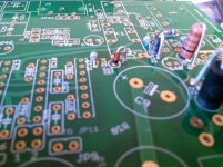
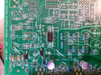
Here is the best photo of the zener in D16 band down and the larger fitting 1N4004 in D15.
Alex
Note the only 1N4004 diode I have installed is the one in pix D15, I had to take an emory board and ever so gently file down the leads to get it in the holes....np. So its not the wrong zener etc..
Here is the best photo of the zener in D16 band down and the larger fitting 1N4004 in D15.
Alex
Note the only 1N4004 diode I have installed is the one in pix D15, I had to take an emory board and ever so gently file down the leads to get it in the holes....np. So its not the wrong zener etc..
Attachments
Last edited:
In the build instructions page 10, where it says "So these are IC11, R70, R79, R83, R84, R85, C49, C50, C61"...
C61 is part of the Zorbel network...so this probably should not be in this list?
Also not on the schematic, near the Zorbel network, there is a note that indicates the parts to be left out R78, R79, C74 and C75, are these correct??
(the build instructions have R86, R87, C60 and C61).
Alex
Good finds!
") You are right on both counts. In addition there was some wording about the damping resistor positions that needed to be updated on the schematic. Both are fixed and a new set of build instructions and schematic are posted out at the Google Drive link. BTW, I can't remember if I've mentioned this, but credit goes out to Limp for sharing the secret of getting Eagle to dump nice sharp & scalable vector schematics! Use the print and print as PDF rather than going the export -> image route.
You are right on both counts. In addition there was some wording about the damping resistor positions that needed to be updated on the schematic. Both are fixed and a new set of build instructions and schematic are posted out at the Google Drive link. BTW, I can't remember if I've mentioned this, but credit goes out to Limp for sharing the secret of getting Eagle to dump nice sharp & scalable vector schematics! Use the print and print as PDF rather than going the export -> image route.I looked at the mouser site for the 1n4004 diodes and the part number in the BOM is for the DO-41 package...so it looks like the holes in the board itself are just too small for this DO041 package lead size...
Alex
Well this has certainly been an interesting find. It would appear that you are right. In the photo build that I did the 1N4004's were one of the few parts where I used a bunch I had on hand rather than the Mouser part I specified. I did get some of those Mouser diodes in though last week and just tried one in MisterRoger's boards that I still have here. Sure enough, doesn't fit. Not sure what exactly is going on there yet, probably an Eagle library error, but there is an easy fix. I have a big pile here of the ones that do fit, so I'll simply send a set out to everyone, no charge of course. Problem solved for this build, and I'll get the Eagle issue corrected before the next board run.
Good find! I'll get those diodes in the mail to everyone on Monday.
Last edited:
T
Thanks very much....great DIY customer service for sure!!
Alex
I've found the problem. When I created that vertical 1N4004 part library I somehow screwed up and used DO-35 sized pads. Then I never noticed the problem because the pile of 1N4004 and 1N4006's I have on hand just happen to have leads sized at the lower end of the 0.072mm - 0.86mm range for DO-41 and fit just fine.
Murphy's Law is still aliive and well. The other few vertical diodes on the board are zeners and really are DO-35, so all is OK there.
I have the problem fixed now and I've re-posted the Gerber files out at the project Google Drive link. I'll mail out those diodes on Monday. Thanks again to Alex for finding this one!
Also - I wanted to say thanks to MisterRogers for letting me move him to the next board run list. I've decided to keep a board or two on hand to use for more detailed build photos (higher rez).
Last edited:
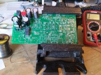
Ok Assembly Step 1 completed...
Including the 12 balancing resistors.
Less the "optional" C62, C63 HF Bypass caps across the electrolytics C7, C8.
Now I must wait for the ac adapter from mouser which has shipped and test the CRC part!! (JP8, JP9).
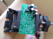
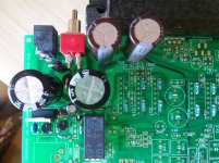
First Pix: Here is the board in my "Vise" its a really heavy drill press vise that doesn't move around much, very stable and allows me to angle if needed.
Second Pix: Top View so far...
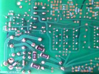
Third Pix: Bottom Board
Fourth Pix...looking pretty!! LOL
Alex
Including the 12 balancing resistors.
Less the "optional" C62, C63 HF Bypass caps across the electrolytics C7, C8.
Now I must wait for the ac adapter from mouser which has shipped and test the CRC part!! (JP8, JP9).
First Pix: Here is the board in my "Vise" its a really heavy drill press vise that doesn't move around much, very stable and allows me to angle if needed.
Second Pix: Top View so far...
Third Pix: Bottom Board
Fourth Pix...looking pretty!! LOL
Alex
Attachments
Turbon,
I can understand the part about funds...I was layed off last October from the Lenovo PC Company. I am 64 yrs young and have gone thru many resource actions are they are called now....train people from China and then watch your job go away and then hey thanks great job but your function is no longer needed here....
Enough whining!! LOL
I decided to retire...and now have lots of time to do projects etc but all things are on a fixed budget here!!
The ODA is not an inexpensive DIY for sure, The parts, case and AC adapter brought this project up to the $250 area.
I think the end result will be worth the time and effort. Agdr has done a really awesome engineering effort on making this ODA a reality.
I really enjoyed building my O2's and am enjoying the ODA build so far.
My back ground is a electronics technican/engineer for 30+ years, done lots of troubleshooting and debug with AC/DC and RF circuits. Had my shares of getting shocked!! I never was in the design part but worked a lot in circuitry to be able to debug things when they are broke!
I had my order in Mouser's project area for a few weeks and sold some headphones I had to fund the project!!
I am waiting on the 24VAC 1/8 amp xfmer from Mouser which by itself in $30! The case is $20 or so as well....
Copper prices and shipping costs all add up now-a-days.
Hope you can get started soon!!
All the Best
Alex
Well I just found my first mixup...no power Yahoo, but FYI there are three sets of SMD resistors that are very similar if your not careful identifying...I just had to remove R78 and R82 which wasn't as bad as I thought it would be...at least the parts didn't go flying across the floor and they weren't hurt in value removing them..
So: R78 and R82 are 499K Relay delay resistors
R8 and R12 are 499 ohm 4x gain resistors
R42 and R43 are 4.99K input bias gnd resistors..
So...its easy to overlook and pick the incorrect ones!!
even checking with a meter before and after installing I missed this.
I was identifying the remainder resistors and labeling them with there respective R numbers and came across 2 that I thought I had already installed!!
oh my.....64 yrs old and half blind...
LOL
Alex
BOM changes! DC null resistor and 5K pot if jumpering R31 and R32
I've made a few BOM changes and just posted the revised BOM out at the project's Google Drive link.
The first is replacing the 4.02K resistors R47, R48, R54, and R58 with 5.49K to better center the DC null trimpot. In the photo build pictures I had to turn the trimpots about 6 half-turns each to zero out the DCoutput offset voltage. The trimpots are 25 turn units - you get a full 12 turns in each direction - so 3 full turns here isn't a problem. The original 4.02K in the BOM work just fine. But I just wanted to get it centered a little better if possible. With the 5.49 K only about 1 turn does the job.
When I mail out the 1N4004 diodes I'm going to send a set of the 5.49K resistors to everyone too, no charge. You can use them if you wish, or just keep using the 4.02Ks. And due to that the mail won't go out until Tuesday - I luckily get next day service from Mouser.
I had orginally designed that circuit to produce about -1.6mV, but in actual practice the NJM4556A chips only needed about -1.1mV to zero their DC offset.
The other change is related to something Alex ran into today in his build. Alex wants to jumper the attentuation resistors R31 and R32 to get the full 10.5Vrms output swing, which is OK and one of the build instruction options. But if a builder is doing that a few things in the BOM have to change. The pot has to change from 1K to 5K for power dissipation reasons. Due to that change the output stage ground return resistors R42 and R43 have to change from 4.99K to 24.9K, and due to that change not as many of the 4.7uF coupling capacitors are needed. Just 2 on each channel will do the job (plus one still needed on each channel for the DC offset null circuit).
The 5K pot and 24.9K ground return resistors will produce more Johnson noise than the 1K / 4.99K pairing, but it still beats the 10K pot and 40.2K ground return resistors in the O2 headamp.
I had information about the attentuation jumpering and the 5K pot & ground return resistor changes in the build instructions for the previous ODA version but looks like I over-deleted. I've just added back some build option information for the various parts. I had deleted several of the build options for this version to simplify things, but over-deleted on this one. I'm still working on the revision and should have the revised build instructions posted tomorrow.
Alex - I've sent you a PM about all this. I have a 5K audio pot here along with the resistor changes. If you've already soldered in your 1K pot just stuff the board in an envelope and send it to me. I have a hakko 808 solder sucker that will get the pot out without any damage to the board, and I'll swap it for the 5K. Wick won't do a good job with the pot. Let me know...
I've made a few BOM changes and just posted the revised BOM out at the project's Google Drive link.
The first is replacing the 4.02K resistors R47, R48, R54, and R58 with 5.49K to better center the DC null trimpot. In the photo build pictures I had to turn the trimpots about 6 half-turns each to zero out the DCoutput offset voltage. The trimpots are 25 turn units - you get a full 12 turns in each direction - so 3 full turns here isn't a problem. The original 4.02K in the BOM work just fine. But I just wanted to get it centered a little better if possible. With the 5.49 K only about 1 turn does the job.
When I mail out the 1N4004 diodes I'm going to send a set of the 5.49K resistors to everyone too, no charge. You can use them if you wish, or just keep using the 4.02Ks. And due to that the mail won't go out until Tuesday - I luckily get next day service from Mouser.
I had orginally designed that circuit to produce about -1.6mV, but in actual practice the NJM4556A chips only needed about -1.1mV to zero their DC offset.
The other change is related to something Alex ran into today in his build. Alex wants to jumper the attentuation resistors R31 and R32 to get the full 10.5Vrms output swing, which is OK and one of the build instruction options. But if a builder is doing that a few things in the BOM have to change. The pot has to change from 1K to 5K for power dissipation reasons. Due to that change the output stage ground return resistors R42 and R43 have to change from 4.99K to 24.9K, and due to that change not as many of the 4.7uF coupling capacitors are needed. Just 2 on each channel will do the job (plus one still needed on each channel for the DC offset null circuit).
The 5K pot and 24.9K ground return resistors will produce more Johnson noise than the 1K / 4.99K pairing, but it still beats the 10K pot and 40.2K ground return resistors in the O2 headamp.
I had information about the attentuation jumpering and the 5K pot & ground return resistor changes in the build instructions for the previous ODA version but looks like I over-deleted. I've just added back some build option information for the various parts. I had deleted several of the build options for this version to simplify things, but over-deleted on this one. I'm still working on the revision and should have the revised build instructions posted tomorrow.
Alex - I've sent you a PM about all this. I have a 5K audio pot here along with the resistor changes. If you've already soldered in your 1K pot just stuff the board in an envelope and send it to me. I have a hakko 808 solder sucker that will get the pot out without any damage to the board, and I'll swap it for the 5K.
Wick won't do a good job with the pot. Let me know...
Last edited:
Ok This is by far the hardest part to solder successfully...the SMD parts are relatively easy compared to this IC5.
WOW!
The hard part is not bridging between the pins due to unsteady hands or an unduly wide soldering tip.
I used a normal tip but used the narrow up down side to slide in and solder.
One side was not to bad the side facing the tall caps was harder due to the caps being in the way with my larger soldering iron.
Glad this one is in and hope it works!!
LOL
Alex
Attachments
Ok This is by far the hardest part to solder successfully...the SMD parts are relatively easy compared to this IC5.
I agree 100%! In my photo build I bridged a couple of the pins on the first pass myself.
So you can see why I had IC5 at this point in the build, before everything else around it. After I did IC5 in that photo build I actually went back and took a second look at fitting in a DIP8 version, but it isn't going to happen. The DIP versions are just so much larger.
Also, back on jumpering the R31 and R32 resistors and the associated pot issue. I know you are back to the 1K pot and keeping the attenuation resistors as per our PM, but another option if someone wants to do that is a panel-mounted external 1K pot with a higher power dissipation rating. That would be the best of both worlds. R31 and R32 jumpered for full voltage swing, but still keep a 1K pot, 4.99K ground return resistors, and all the 4.7uF capacitors for low noise. I see Mouser has a 29mm dual-gang panel-mount audio taper pot, rated at 250mW, for just $2.70 or so. But at 29mm it (just barely) wouldn't fit between the top of the 4.7uF caps and the top of the B4-080 case.
Today wound up being busier than expected so I haven't had a chance to do those build instruction updates. Most likely tomorrow.
Last edited:
Ok This is by far the hardest part to solder successfully...the SMD parts are relatively easy compared to this IC5.
WOW!
The hard part is not bridging between the pins due to unsteady hands or an unduly wide soldering tip.
I used a normal tip but used the narrow up down side to slide in and solder.
One side was not to bad the side facing the tall caps was harder due to the caps being in the way with my larger soldering iron.
Glad this one is in and hope it works!!
LOL
Alex
Hi Alex, I usually put some solder on the pads and then add pressure on the chip. Then just heat the pins until the solder melts and spreads onto the pin.
Regards
Understand for now ...I am at the point in the build instructions where I am installing R31, and R32 ...LOL. Good Timing again.
So the 9mm 1K pot is only good for 25mw and with the 1K attentuation resistor and 10Vrms out of the gain stage, maximum, you are at 25mW.
I don think I will ever be cranking up the volume to this level so even the default with R31 and R32 in and the 1K pot we should be ok.
I think I will go for the attenuation resistors in for now and the 1k pot get the amp built and working and then play around with this and the bass boost etc...
Just installed IC1 and IC2 another eye test!!
When the care package arrives I will be really close....hope the xfmr arrives today.
Turbon great idea as well.
I took a small piece of scotch tape, yes scotch tape and taped the IC1 and IC2 to the board carefully positioned and left one side of the legs in the clear to solder and it made life a whole lot easier!
Later, back to soldering!
Alex
- Home
- Amplifiers
- Headphone Systems
- A version of an O2 Desktop Amp (ODA)