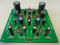
A while ago I made a pcb for a high power headphone amp that can drive all impedances. It is a simple design with an opamp followed by a pair of diode biassed BD139/140 or BC327/337 for more current. The PCB has been used by several people and it works really well for a low price. Total price is 20-25 euro without housing.
Attachments
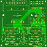
A new version is almost done. It will be ordered soon.
It now has a transformer on the PCB as well.
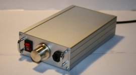
It fits in standard housings for 100x160mm PCBs, leaving room for potmeter, connectors etc. See attachment for an example of the case someone made with my PCB inside") I think it looks really nice.
I think it looks really nice.
It now has a transformer on the PCB as well.
It fits in standard housings for 100x160mm PCBs, leaving room for potmeter, connectors etc. See attachment for an example of the case someone made with my PCB inside
I think it looks really nice.Attachments
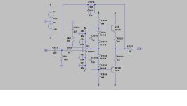
gnd is connected "wrong way around" - the xfmr ct to rectifier/cap gnd is a "dirty gnd" large 2x line frequency charging current pulses flow in it, the amp circuitry should connect to the regulator side of the reservoir C gnd, let the xfmr ct trace be a stub
the outline suggests an EI xfmr - may radiate mag field causing hum so close to the amp circuitry, traces - if it has a "belly band" you may want to rotate 90 - or allow room for some iron/low carbon steel sheet shielding
for added stability I would add a inner feedback C to each op amp that could be a stuffing option
local nF bypass caps at the op amp should be connected right at the op amp ps pins, choose one size - the "universal" hole pattern adds inductance - I would use different circuit rather than rework part values
but probably little need for the 22 uF C11/20 so close to the reg
the pull-up/down R for the Vbias may be too high for the worst case range of output Q hfe, may limit current at high Vswing, low frequency
Last edited:
- Status
- This old topic is closed. If you want to reopen this topic, contact a moderator using the "Report Post" button.