Yes, it does.
Some of the reasons:
The values can be too low for the amplifier to drive (op-amps)
If the values are selected low and there is a capacitor to ground (for AC gain but DC gain =1 for reduced output offset) then the capacitor can become rather large.
If the values are too high the offset voltage due to input currents can increase if not balanced...(Offset drift may still be an issue)
If the values are too high then the input capacitance can cause a phase shift in feedback, causing limits with frequency response, instability or oscillation.
If you look at the datasheets for very high frequency/video amplifiers the feedback resistors are low compared to audio applications...The voltage swing is also small...1-2V
I think there are also noise issues with higher resistance...Someone more experienced should address this aspect of the question.
Hope that helps.
Resistors generate thermal/Johnson noise, which in voltage terms is proportional to the square root of the resistance. Bigger value resistor means more thermal noise. However, there may be little point in reducing noise much below the noise already coming from the source.
Yes, the noise difference between 10k feedback resistors and 1k resistors is dramatic, at least in simulation. I prefer to use the lowest I can get away with.
What I do is figure out the expected load for the opamp, and then put that in parallel with any feedback resistor values, and the result has to be greater than the minimum recommended load for the opamp. In order to provide greater drive power, I add a buffer inside the feedback loop, like the BUF634. The over all result is lower noise.
In an opamp-buffer-headphones setup, is the load to the opamp largely the resistor between the opamp and buffer?
I don't put a resistor between them. But, if there was one, then that'd be it.
if is in in series with the (non-inverting) buffer input then the load is the buffer input Z, typically MegOhm || pF
a "Class A bias" R from the op amp output to one of the PS rails does count as load
Yes, of course, should have clarified, sorry!
i intend to use only opa1612 because i like how it sound,has also very good specs
-i always set the gain opamp -1st, as multiple feedback LPF (with 56 and 100) i WOULD get excellent q factor and very low noise.
Also intend using Opa1612 for buffer ,inverting unity gain voltage follower.
The problem is that datasheets don't specify always minimum feedback res like for LT1028.
My output voltage should be 6V RMS direct connection to amplifier that are found as kit.
input can be a smartphone or My audiophile DAP the DX50 ,intend to use same layout for DAC I/V
The data sheets will specify a maximum output current and that value can be used to derive the minimum feedback network resistance/impedance the device can drive. For minimum distortion you probably need to increase those calculated values by at least 100%. And don't forget the load of whatever the preamp is connected too.
For a unity gain inverting buffer an acceptable "Rin" partly decides your choice because that resistor value determines the input impedance.
For a unity gain inverting buffer an acceptable "Rin" partly decides your choice because that resistor value determines the input impedance.
As Mooly suggested, the data sheet shows about 40mA max current...maybe 45mA if you can keep it cool.
6Vrms is 8.484Vp
8.484Vp / 0.04A = 212.1 ohms.
This number would be what I would use for the absolute lowest value of resistance for the load. (feedback resistors and connecting cable capacitance and amplifier input impedance)
However,
There is little data on power dissipation or junction to ambient (or board) thermal impedance.
You might heat up the amp when operating at this level with this load.
If you still want to try it, please keep a finger on the amp.
If it is too hot to touch, there is a problem. (IMHO)
You could reduce the supply to about 12V to reduce heating if it becomes a problem.
Good luck.
")
6Vrms is 8.484Vp
8.484Vp / 0.04A = 212.1 ohms.
This number would be what I would use for the absolute lowest value of resistance for the load. (feedback resistors and connecting cable capacitance and amplifier input impedance)
However,
There is little data on power dissipation or junction to ambient (or board) thermal impedance.
You might heat up the amp when operating at this level with this load.
If you still want to try it, please keep a finger on the amp.
If it is too hot to touch, there is a problem. (IMHO)
You could reduce the supply to about 12V to reduce heating if it becomes a problem.
Good luck.
Hi,
Its utterly inane to to use a feedback loop that is harder to drive
than the intended load here, here minimum 3 times the load.
A high impedance feedback loop will add noise, so for a
headphone amplifier 5 to 10 times load is very reasonable,
though you can go higher and most do, without any real issues.
Power amplifiers get along fine with a ~ 30K feedback loop,
with an ~ 1K input resistor defining noise, so shedloads
less lop loading, many headphone amps the same.
rgds, sreten.
Last edited:
40mA is a typical short circuit output.
When you look at output voltage vs load resistance you will find that gross distortion sets in soon after going beyond half the short circuit current.
i.e. the usable maximum output current is probably around 20mA.
A 600ohm resistive output load in parallel with a 2k feedback resistor results in ~460r
6Vac pushes ~18mA through that combined load.
You then need to add on an allowance for capacitance, both parasitic and deliberate, that takes more current from the output stage.
There is more to electronic design than taking your favourite opamp and placing it in a seriously suboptimal circuit. A poor opamp in a good circuit is likely to outperform a wonderful opamp in a bad circuit. Circuit theory comes first. Get that right, then start to worry about minor issues like opamp fashion.
Lets get specific. How much gain in the opamp circuit? What is the load? If this is a headphone amp, it is likely the gain can be set to ~5. So, I wouldnt worry much about noise gain. If your headphones are >35 ohms, you can probably use an LT1497 which current limits at 125mA or so. I'm building a simple headphone amp based on the 1497. Powering it from a micro USB, takes +5 in and create a -5 rail. No coupling caps required is the big benefit here, caps take up space and provide a significant source of potential distortion (depends on dielectric type, voltage rating, etc). In my case, I hv audio technica M35s which are 65 ohms and almost purely resistive (i measured). I needed something small and light to provide a gain of 5 (or so) from my iphone while I sit at a computer. Sometimes I need to really crank the tunes. I'll get back with results after the build.
Last edited:
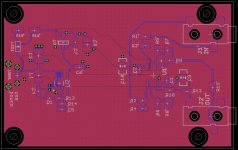
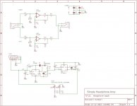
Update: Here's the board I built (1.8"x2.8") that is USB powered that derives the +5V to generate a split supply, +/-5V. I have audio technica M35 headphones which are 65 ohms. I wanted to have a gain of 5 to boost the level from my iphone, and both intended to be powered from a computer's USB ports. Sometimes I like to crank it at work. The max output is ~2.5V rms which is close to the max allowed for the headphones, 100mW.
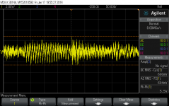
I tested the amp and looked at the supply rails while pushed to the max. The inverting switcher does have occasional problems under severe rock passages with heavy bass. More decoupling is needed. Also plan to use a mini USB connector instead of micro B. Also looking into seeing if the 3483 can be operated in continuous mode (runs burst mode now). While music was running, I put a scope on the output. When I saw the drops outs of the -5V rail, I was somewhat surprised how little effect it had on the sound. The rail was dropping hundreds of mV. The op-amp's PSRR at work. But as you can see from the scope shot, the peaks were hitting about 3V which was very loud. Let me add, this little amp sounds very clean.
I tested the amp and looked at the supply rails while pushed to the max. The inverting switcher does have occasional problems under severe rock passages with heavy bass. More decoupling is needed. Also plan to use a mini USB connector instead of micro B. Also looking into seeing if the 3483 can be operated in continuous mode (runs burst mode now). While music was running, I put a scope on the output. When I saw the drops outs of the -5V rail, I was somewhat surprised how little effect it had on the sound. The rail was dropping hundreds of mV. The op-amp's PSRR at work. But as you can see from the scope shot, the peaks were hitting about 3V which was very loud. Let me add, this little amp sounds very clean.
Attachments
- Status
- This old topic is closed. If you want to reopen this topic, contact a moderator using the "Report Post" button.
- Home
- Amplifiers
- Headphone Systems
- Feedback resistor size - opamps