Congratulations! Some questions :
What is the total ma or power consumption of the amp?Is there a possibility to get the pcb from you? Are the regulators on the same board?
By the way I did once connect my headphones to my aleph 5 monos but the hum levels were way too high for headphone listening.
What is the total ma or power consumption of the amp?Is there a possibility to get the pcb from you? Are the regulators on the same board?
By the way I did once connect my headphones to my aleph 5 monos but the hum levels were way too high for headphone listening.
Too cool for school
One of the nicest jobs I have seen on the forum. The design looks great and is only overkill from the attention to design details and not for parts count. For the penny pinchers I would say that one could use J202 fets for current regulators in place of the jfet two terminal current source. I would try the Zetex ZVP3310 for the current sources for the J109 jfet pairs. Zener protection for the mosfet gates is generally a good idea too. I wish I had one. When are circuit boards available?
One of the nicest jobs I have seen on the forum. The design looks great and is only overkill from the attention to design details and not for parts count. For the penny pinchers I would say that one could use J202 fets for current regulators in place of the jfet two terminal current source. I would try the Zetex ZVP3310 for the current sources for the J109 jfet pairs. Zener protection for the mosfet gates is generally a good idea too. I wish I had one. When are circuit boards available?
Yes that what I am saying
JWB,
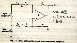
According to your schematics, you have a non-inverting input and only one input. The output is single ended and not balanced. A balanced amp always has two inputs that are non inverting and a inverting. That’s the only way you can get right of a common mode signal like 60Hz on at the outputs.
Audio amp don't have balanced input they have diff amps but that in it's self does not make it balanced. The Aleph is a diff amp with balanced input but not in the purest form.
Having said that, I think you done a nice job with the circuit and construction.
Regards
Attachments
Re: Too cool for school


I have pcb's ready for sale. I have started with 10000 boards. I think I can sell them in a week. Are you interested?Fred Dieckmann said:I wish I had one. When are circuit boards available?


Re: Too cool for school
Knock me over with a feather! I think Fred and I have exchanged three or four cordial messages. Consecutively even. Peace and prosperity
As grataku vigorously points out, he has first claim on my one and only extra printed circuit board. The rest of you should consider your luck. If my Design for Manufacturability instructor saw this, he would fail me retroactively. There are power transistors mounted under the middle of the board, surface mount components in impossible-to-rework positions, no component references on the silkscreen, and so forth. Also the mounting and cooling is specific to the Sun 411 SCSI disk chassis. Only the most intrepid will be happy trying to build it. I'll happily post my CAD files if someone wants to use this design as a starting point.
To the other question, the design dissipates 16W, and it's capable of over 700mW into 32Ω cans. I'm thinking of lowering the power ability to something like 300mW to only produce 9W, for a little less toasty running.
Jam: I've only been listening to it in Aleph mode so far. Will report on Zen performance later. The other jumper, which shorts the DC feedback cap, is very useful for quickly adjusting the DC offset. With a 12-turn pot I can get the offset below 100µV.
Fred Dieckmann said:One of the nicest jobs I have seen on the forum. The design looks great and is only overkill from the attention to design details and not for parts count. For the penny pinchers I would say that one could use J202 fets for current regulators in place of the jfet two terminal current source. I would try the Zetex ZVP3310 for the current sources for the J109 jfet pairs. Zener protection for the mosfet gates is generally a good idea too. I wish I had one. When are circuit boards available?
Knock me over with a feather! I think Fred and I have exchanged three or four cordial messages. Consecutively even. Peace and prosperity

As grataku vigorously points out, he has first claim on my one and only extra printed circuit board. The rest of you should consider your luck. If my Design for Manufacturability instructor saw this, he would fail me retroactively. There are power transistors mounted under the middle of the board, surface mount components in impossible-to-rework positions, no component references on the silkscreen, and so forth. Also the mounting and cooling is specific to the Sun 411 SCSI disk chassis. Only the most intrepid will be happy trying to build it. I'll happily post my CAD files if someone wants to use this design as a starting point.
To the other question, the design dissipates 16W, and it's capable of over 700mW into 32Ω cans. I'm thinking of lowering the power ability to something like 300mW to only produce 9W, for a little less toasty running.
Jam: I've only been listening to it in Aleph mode so far. Will report on Zen performance later. The other jumper, which shorts the DC feedback cap, is very useful for quickly adjusting the DC offset. With a 12-turn pot I can get the offset below 100µV.
So, If I say that I have improved the Jung regulator with a better current source for the pass device, I mean to say only that my current source has a higher Z (about a megohm, by my reckoning) than the original. Strictly speaking, you may not think this makes any difference in the final product, and you may not think it rises to the level of "improvement".
I agree that the subing of a JFET diode for D26 etc. (ref your PDF sch.) will improve things for the regulator as shown. This has been analyzed and discussed in the 'super regs" thread, and is a simple, effective change (albeit one slightly more costly) if one doesn't wish to use a pre-reg. I also believe it has sonic benefits as well, but I don't think anyone in the referenced thread has evaluated it in exactly this context, alone. At least they haven't reported it.
I disagree that a JFET diode is also warranted as the feed for the LM329 ref. diodes for D30 etc. (ref your PDF sch. again) , unless one wishes to keep the LM329 Iz constant as output voltage changes. A JFET really can't be justified from a pure noise standpoint, as the published network with a 5k feed R, the LM329, and a 499 ohm/120uF RC filter has attenuations of
>100dB/100Hz and >140dB/100kHz. This noise suppression is sufficient to make the audio band noise level be virtually dominated by the op amp used, not the reference circutry.
JWB and I have discussed this latter point to some degree via email, and while I don't agree the JFET is really needed, it certainly should not hurt things (performance-wise).
I have been working on one form or another of this regulator circuit for a long time now (approaching ten years?), and I do welcome inputs and questions. Often, a prediscussion of a proposed variant may help expose potential problems. For example, in JWB's circuit he shows a 0.1uF bypass across the regulator output. This is almost an open invitation to oscillation, as has been discussed here and elsewhere. I'd suggest leaving it out, to eliminate that possibility.
I agree with the other comments that this is a nice looking design, and no doubt it does sound very good. It is nice to see such quality work being shared with others.
Walt Jung
JBW,
I learned alot by hanging out on this forum, the package you put together represent the synthesis of all the knowledge that is contained in this forum. Basically, good design practice on all aspect of the circuit.
Fred finds the idea of the current sink to the negative rail irresistible ;-).
So I will happily live with the minor shortcoming that you say are present with your layout.
"Knock me over with a feather!"
Well, I can't keep track of everybody I have crossed swords with...... I am much more interested in the results of someone's work than personalities. You have done the work and did a fine job.
Hold this in contrast with some who wants to be popular but never delivers on things he says he is designing. I think the forum is moving on to another level for maybe a small, but growing number of people with the time and resources to push there designs to the State of the Art. I have seen some design on the level of some of the best commercial stuff, right here on the forum. With the presence of some very good and well known audio designers and the level motivation of the members, I see some very interesting projects going. Spice models and disscussion of topologies are going to leave people behind and let others learn enough to build interesting equipment and enjoy the challenge of learning new design techniques.
WaltJ said:
I have been working on one form or another of this regulator circuit for a long time now (approaching ten years?), and I do welcome inputs and questions. Often, a prediscussion of a proposed variant may help expose potential problems. For example, in JWB's circuit he shows a 0.1uF bypass across the regulator output. This is almost an open invitation to oscillation, as has been discussed here and elsewhere. I'd suggest leaving it out, to eliminate that possibility.
Oh yes, do be careful with this one. This is another carryover from my Sulzer experiments, where it improves step load response considerably. A thoughtful consideration of layout and trace impedance is (always!) necessary. Leaving the cap out is of course an option. That's why this design has so many jumpers and options: experiment!
BTW, in my experiments ALW's 10000pF cap across Vsense is prone to oscillation, depending on the distance to the sense point. However I was not using ALW's printed circuit, and I was using the AD797 he seems to recommend. Different situation, same pitfall.
Deja Vu all over again
As posted by Mr. Jung
"A JFET really can't be justified from a pure noise standpoint, as the published network with a 5k feed R, the LM329, and a 499 ohm/120uF RC filter has attenuations of >100dB/100Hz"
At little expansion on where this number comes from might be in order, I hope you don't mind if I elaborate. The dynamic impedance of the LM329 is about 0.5 ohms I believe. This with a 5K bias resistor gives about 80 dB of attenuation at the LM329. The 500 ohm 120uF filter has a corner frequency of around 2.5 Hz and is down a little over 30 dB at 100 Hz. This gives a rejection over 80 + 30 or > 110 dB at 100 Hz.
"Well, I can't keep track of everybody I have crossed swords with...... I am much more interested in the results of someone's work than personalities. You have done the work and did a fine job."
Nicely put Hannibal, I too hate rude undeserving people. Pro Quo.
I won't repeat the rest of your post, it belong in the Paris sewer.
Have you ever thought about the many other countless members that have designed, modified or based their construction on sound theory or best practise. (otherwise unpublished works).
Perhaps you should stand guard at the firewall of the passdiy.com with your Sword of Honour and pass (excuse the pun) an engineering certification so that each project is worth publishing, just to be on the safe side.
I would be delighted to see a full account of the design and construction of your active crossover recently pictured in another thread recently. It would be a world first.
http://www.diyaudio.com/forums/showthread.php?postid=268824#post268824
It reminded me of my eldest nephew's first ever electronics project using solar panels to operate a radio, only his finished project was very well presented and won an award.
Ta Ta for now,
macka
:
macka said:Blah blah blah
Please take your pointless attacks somewhere else.
Pardon, whats good for one is good for another in these forums apparently.
Beside 's my inbox is spilling over with messages of agreement.
You obviously share Freds hair brush.
The point is no body likes insults but Fred thinks he can sneer in anyones thread about anything that suits him at the time purely because of the soft **** mentality of the on lookers who then go on to copy him.
Well obviously that ain't so any more.
macka
- Status
- This old topic is closed. If you want to reopen this topic, contact a moderator using the "Report Post" button.
- Home
- Amplifiers
- Headphone Systems
- jwb's ultimate aleph headphone amp


