Hi,
I'd like to DIY a simple device that uses one 9v battery to mix 4 iPads (4 inputs) that goes to 4 outputs that can drive 4 earbud-type earphones.
This is so 4 people could plug into this device and listen to one another.
Been looking at the headphone distribution amp schematics but they're usually either many inputs to single output (mixer) to one input to many outputs (distribution).
I'm a relative noob in electronics but can solder and have done audio kits before")
Can someone please help?
Thanks!
I'd like to DIY a simple device that uses one 9v battery to mix 4 iPads (4 inputs) that goes to 4 outputs that can drive 4 earbud-type earphones.
This is so 4 people could plug into this device and listen to one another.
Been looking at the headphone distribution amp schematics but they're usually either many inputs to single output (mixer) to one input to many outputs (distribution).
I'm a relative noob in electronics but can solder and have done audio kits before
Can someone please help?
Thanks!
mix 4 iPads (4 inputs) that goes to 4 outputs that can drive 4 earbud-type earphones.
There's your answer. You need to build both the mixer and distribution amps, then connect them together. The single output from the mixer becomes the distribution input that is sent to the 4 headphones.Been looking at the headphone distribution amp schematics but they're usually either many inputs to single output (mixer) to one input to many outputs (distribution).
Thanks for the reply!
In that case, how long would an average 9v battery last to power these 2 circuits?
I teach on the iPad and would like to group 4 students to a group, in class, for an ensemble!
Also, any particular links you could point me to for schematics of these 2 circuits?
Thanks again!
In that case, how long would an average 9v battery last to power these 2 circuits?
I teach on the iPad and would like to group 4 students to a group, in class, for an ensemble!
Also, any particular links you could point me to for schematics of these 2 circuits?
Thanks again!
It's hard to say just how long a 9V battery would last. 10 hours or thereabouts? Rechargeables would have less run time, but be cheaper than buying disposable primary cells.
Is the tether of a wall wart supply too inconvenient? I like to avoid 9V batteries whenever I can. What about two small 6V SLA rechargeables? Those would last all day long and could be recharged overnight, and be easy to design for a bipolar supply.
I don't have any links to post right now. These are typical application circuits that can be found in datasheets and app notes. Using op amps such as NE5532 or OPA2134 should work great.
Hi,
If a 9v battery can last about 10hrs, it'll do just fine!
In fact if a 9v rechargeable is a little shorter, it'll still do fine. I just don't want a 1hr battery life that I'd have to charge in between class periods.in any case, music lessons are only about twice a day or so.
I'm not planning on SLA-types as I wanted the circuit to be inside a 4"x4" casing so its easily collected and stored after lessons
Will search out for any ready circuits for the chips you've suggested. Are LM386 chips workable too?
Thanks again!
Look at Figure 18a and 18b here:
Designing An Opamp Headphone Amplifier | HeadWize
Designing An Opamp Headphone Amplifier | HeadWize
Hi,
I found a 2W+2W stereo amp kit that I was wondering, could be easily modified to do my 4in-4out headphone "distributor"
Question is, for the input and output, what value capacitor and/or resistor should I change these to, in order for:
1) 4 passive inputs hooked up to the input and
2) 4 outputs branched out from the current spkr out to drive 4 "typical" iPad-type ear pods?
Would it work?
Thank you for any advice!

Yes, you could do that to simplify the build. At each input connection, place a 10uF capacitor and 10k resistor in series. The other ends of the resistors then all connect to the 10k potentiometer shown in the schematic. Replace the 220uF output capacitor with a 1000uF capacitor, and connect each of the output jacks to it.
And I would power it from four 1.5V cells instead of a 9V battery.
And I would power it from four 1.5V cells instead of a 9V battery.
Last edited:
Much longer and cheaper run time.One more question, why would a 6v power supply suffice instead of 9v?
You should have plenty of output so the extra voltage isn't needed.
Much longer and cheaper run time.
You should have plenty of output so the extra voltage isn't needed.
Hi, ok will change it to 6v instead then.
One other thing I just noticed upon inspecting the kit.
If you refer to the image I attached in my earlier post again, the schematics show the 10uF capacitor at the input with the positive towards the input. On inspecting the kit PCB, I noticed the "+" is facing the 10k potentiometer, instead! In other words the input connects to the -ve of the 10uF cap (according to the PCB)
Now, which should I follow? Coz this would mean that when I attach the other capacitor-resistor inputs(to mix the 4 inputs together), I would follow the same orientation,ie, input to -ve of the cap lead?
Is that right?
Thank you for all your help!
Go by the schematic orientation, but don't install C1. The four inputs replace it and connect directly to the potentiometer.
Thanks. Yes, I was just using C1 as the starting lead for the 1st input (in series with a resistor, of course)
Alrighty...now to warm up the iron
Hi, in January, you gave some tips on how to modify an amp schematic to a mixer/headphone amp combo.
I finally managed to get this up and running successfully!!
However, I was wondering if I could get your advice again on the fact that the trim pot of 10k came up rather sensitive when I set the volume. From a minimum setting, I only needed to turn up less than a quarter turn before it became too loud!
What's the easiest way to decrease the volume sensitivity so that I can set the trim pot to around midway for a "comfortable" level?
Thanks!
Go by the schematic orientation, but don't install C1. The four inputs replace it and connect directly to the potentiometer.
Last edited:
Sorry for the delay. Either I just missed your message or it didn't show up in my subscribed thread list.What's the easiest way to decrease the volume sensitivity so that I can set the trim pot to around midway for a "comfortable" level?
Thanks!
Probably the easiest would be to put a series resistor on the input, just ahead of the 10k pot. I'd start with about 4.7kΩ and adjust that value up or down as necessary.
 Cool! And thanks for taking the time to reply! Was begin to wonder if you just happened to browse this thread that time only!
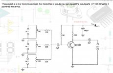
 On another similar note, I "suddenly" got this urge to make things go even smaller(!!) so, was wondering if I used the same capacitor values for the input and output that were suggested (10uF for each input and 1000uF for the output) with this (attached) BC109-based amp, would it work?
Thanks!
Attachments
Last edited:
The capacitors form a high-pass filter with the accompanying resistances. Fc = 1/2*pi*R*C
Assuming a high input impedance at the chip itself, the signal sees only the potentiometer resistance (approximately). 10μF at the input is fine with the 10k-15k potentiometer/series resistor value; it would also work as the coupling cap between mixer and distribution amp, if such coupling is required.
At the distribution output, it is a different situation. There, the circuit is feeding the relatively low-impedance headphones. The lower impedance demands a higher value capacitor to maintain the low frequency crossover point.
For 32Ω headphones, I wouldn't go lower than 470μF, which puts Fc at about 11Hz.
- Status
- This old topic is closed. If you want to reopen this topic, contact a moderator using the "Report Post" button.
- Home
- Amplifiers
- Headphone Systems
- Headphone distribution schematics