Simple to build and great performance.
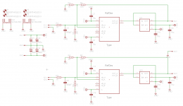
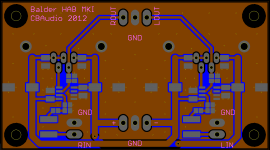
Using OPA2134 and BUF634, could have used OPA134 but OPA2134 made it simpler to layout and the extra cost is negligible.
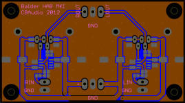
Double sided board with solid groundplane on the bottom layer, tracks on top layer. The connectors, BUF634 and heatsinks are TH, everything else is SMD.
Smallest components are 0805 size.
Board size is 90mm x 50mm.
Using OPA2134 and BUF634, could have used OPA134 but OPA2134 made it simpler to layout and the extra cost is negligible.
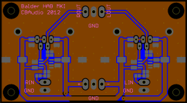
Double sided board with solid groundplane on the bottom layer, tracks on top layer. The connectors, BUF634 and heatsinks are TH, everything else is SMD.
Smallest components are 0805 size.
Board size is 90mm x 50mm.
Attachments
Last edited:
just a tip - not always a good idea to leave unused inputs unterminated on parts that share power rails ...
mlloyd1
You're right, I'll fix that asap.
Balanced Option?
Hello,
@ Neutrality,
My I propose to use full potential of this intend circuit and go also a Balanced (XLR) version, full use of OPA2134 & just add two more BUF634 chips, and You'll have a full balanced HeadhPh. Amp with great usability and top sound, directly from eg. a balanced I/V conv. stage which can be also mounted in an enclosure of the xx player or inside eg. a Sabre DAC encl.and use its dig. volume control.
This would be top sound from intend circuit - balanced all the way, & sound would be a whole range better than SE.
Maybe just for tough?
Cheers
Hi.
Well, I am not really into the whole balanced drive thing, I am more than happy with single ended. So basically it comes down to the fact that I could do a balanced version, but since I do not see a need for it, it will stay single ended.
Sorry.
")
You could also use the second op-amps for DC servos. Just take a look at the LME49600 datasheet for an example.
I know about DC servos and have used them before in my discrete Class A headphone amplifiers.
In this application a DC Servo is not really needed.
In this application a DC Servo is not really needed.
I just remembered that it doesn't even get rid of all the output offset anyway. It only seems to null any input offset, there is still device offset present on the outputs.
I just remembered that it doesn't even get rid of all the output offset anyway. It only seems to null any input offset, there is still device offset present on the outputs.
Well, the output offset in a OPA2134+BUF634 headphone amplifier is the offset of the OPA2134, which is only a few mV worst case.
But in cases where you have a source with a lot of offset, a DC servo could be a good idea, since that offset would otherwise be amplified by the gain of the OPA2134+BUF634 and appear at the output.
So I am looking into adding a DC servo.
Resistors and capacitors for the DC servo will be SMD and mounted on the bottom layer.
Last edited:
I've built quite a few different amps based on the LME49600 circuit (with servo), and even though it nulls any offset injected into the inputs, there has always been some offset on the outputs without an input signal present or even with the input grounded. I'm not experienced enough to figure out why that is.
I've built quite a few different amps based on the LME49600 circuit (with servo), and even though it nulls any offset injected into the inputs, there has always been some offset on the outputs without an input signal present or even with the input grounded. I'm not experienced enough to figure out why that is.
How much are we talking about? When I use a DC Servo on my other designs I get an offset of +/- a few mV, the output offset basically swings around 0V, +/- a few mV. This is quite normal behaviour and nothing to be worried about
i've built 4 different iterations of the wire with lme49600/10, none have any offset worth mentioning. LPUHP had some (~25-30mV) without the input grounded or connected, thats only logical as its a floating amp, with a floating power supply and a floating input, its a hugely wideband amp so will amplify noise pickup. the LPUHP has 21db of gain, far more than the other 3, it vanished when the input was grounded or fed signal. the others had none to speak of at any time.
a servo isnt going to stop a sudden an extreme transient from outside the amp, or a sudden failure inside the amp
so its my opinion the servo doesnt solve anythung more than good layout would and brings its own set of problems, if the servo fails....
a servo isnt going to stop a sudden an extreme transient from outside the amp, or a sudden failure inside the amp
so its my opinion the servo doesnt solve anythung more than good layout would and brings its own set of problems, if the servo fails....
Last edited:
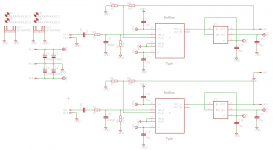
Changed to OPA2132 instead of OPA2134, more or less same performance but half the worst case input offset.
I dropped the idea of using a DC Servo and instead I added an 1uF input cap and increased R7/R8 to 100K so I would still be getting a good and extended low end response.
Input DC blocking cap will be a Wima film type in SMD, cap in RC filter will be a Panasonic film cap also in SMD.
Electrolytes will be 16V/1000uF os-cons.
Going with +/-12 VDC, more than enough power for my 250 Ohm DT880 PRO.
Attachments
Got it up and running today together with my ES9023 DAC.
First impressions are very positive.
Detailed without being bright and plenty of control and power.
Tomorrow I will try it with a pair of cheap Sennheiser HD415 110dB/32 Ohm headphones as well as my "highendish" 96dB/250 Ohm Beyerdynamic DT 880 Pro headphones.
First impressions are very positive.
Detailed without being bright and plenty of control and power.
Tomorrow I will try it with a pair of cheap Sennheiser HD415 110dB/32 Ohm headphones as well as my "highendish" 96dB/250 Ohm Beyerdynamic DT 880 Pro headphones.
- Status
- This old topic is closed. If you want to reopen this topic, contact a moderator using the "Report Post" button.
- Home
- Amplifiers
- Headphone Systems
- Balder, OPA2134+BUF634 Headphone Amplifier