Hey Diy'ers,
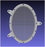
I've made this stator to be used for a single stator electrostatic headphone (illustrated in attachments).
However, I realize there's some writing here at DIYaudio & also elsewhere about single stator headphones having higher distortion than two stator designs, yet can one of explain why this should be so?
My own thoughts on this are:
1. The full stator rod surface is very, very close to the membrane so the electric field will vary very little when the membrane moves. The membrane is a high resistance type.
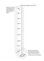
2. Also, since the membrane is very close to the flat stators the electric field variation when the membrane moves will be a linear function and not a square function as it would have been had the stators been an electric point source relative to the membrane. I have attached an illustration of this.
So, I wonder if the high distortion considered to be associated with single stator ES headphones somehow could be a remnant of the past - or if there are other factors that I don't take into consideration?
Insights appreciated")
Jesper
I've made this stator to be used for a single stator electrostatic headphone (illustrated in attachments).
However, I realize there's some writing here at DIYaudio & also elsewhere about single stator headphones having higher distortion than two stator designs, yet can one of explain why this should be so?
My own thoughts on this are:
1. The full stator rod surface is very, very close to the membrane so the electric field will vary very little when the membrane moves. The membrane is a high resistance type.
2. Also, since the membrane is very close to the flat stators the electric field variation when the membrane moves will be a linear function and not a square function as it would have been had the stators been an electric point source relative to the membrane. I have attached an illustration of this.
So, I wonder if the high distortion considered to be associated with single stator ES headphones somehow could be a remnant of the past - or if there are other factors that I don't take into consideration?
Insights appreciated
Jesper
Attachments
Hi again,
I just noticed that I've posted a thread here with a similar question some time ago. If you are interested it is here:
http://www.diyaudio.com/forums/headphone-systems/160082-single-stator-electrostatic-headphone.html
My apology for this - have been looking into many topics lately so it slipped... However, the link in post #2 by Godfrey is no longer active so if one of you knows of a new link for a similar overview I'd appreciate this.
Best wishes,
Jesper
Hi,
both Your assumtions are wrong.
1) the electrical field density varies quadratically with distance. Its just that the field strength increases with smaller D/S-distance, hence the force acting upon the membrane increases with smaller distances. The quadratical relationship applies to any position of the membrane. As such assumption 2 doesn´t apply also. It is just so, that a smaller range of membrane excursion also means less variation in electrical field strength hence less variation of force. Ever decreasing the excursion and the movement approaches a linear movement (though it actually never reaches the linear condition). It is the same as calculating the Derivative of a mathematical function. Since distortion-free working required a true linear relationship, low THD can only be achieved within a very small excursion range.
This should also answer Your last Q. No, physics haven´t changed since the early days.
SE-ESLs inherently distort.
jauu
Calvin
ps. The second sketch contains a mistake. The formula for a circular membrane surface is Pi x r². In praxis under biased conditions the shape would rather follow a chain-contour. But for small excursions the circle formula suffices (talking about a few tenths of an mm). The surface does indeed change but by a miniscule and insignificant amount only. What changes considerably though is the capacitance of the ESL capsule.
Hi Jesper.
That's a beautiful stator. How did you make it? It looks like some kind of plastic so I guess you'll have to apply some sort of conductive coating?
As explained in the other thread, the distortion is primarily because the force on the membrane is proportional to the square of the voltage between it and the stator. It's not a linear function, even ignoring the movement of the membrane.
Cheers - Godfrey
That's a beautiful stator. How did you make it? It looks like some kind of plastic so I guess you'll have to apply some sort of conductive coating?
Problem 1: Unless the membrane is stretched very tight, it will get sucked on to the stator.The full stator rod surface is very, very close to the membrane...
Problem 2: That won't work, it needs to be relatively low resistance. The resistance and the capacitance between the membrane and stator form an electrical low pass filter. If the resistance is too high, the treble will be rolled off.The membrane is a high resistance type.
As explained in the other thread, the distortion is primarily because the force on the membrane is proportional to the square of the voltage between it and the stator. It's not a linear function, even ignoring the movement of the membrane.
Cheers - Godfrey
Hi both,
& thanks for your replies ;-)
@godfrey: Thank you also for your kind words about the stators I really like the shape myself - it appears aesthetically harmonious and appealing to me, and I hope the shaping is also feasible sound-wise. E.g. the long/short axes are dimensioned so that their longest distances corresponds with the frequency distance of a fifth on my piano - the tonal distance that sounded most pleasing to me. The shape is an ellipse and so is the shape of the rods crossing the frame (long axis perpendicular to the membrane surface - to stiffen the rod on the axis of membrane movement). Hope this supports the sound ...
As it is I made the stators in Moi3D:
MoI, 3D modeling for designers and artists
If you are interested there's a free 30 days trial version which can be downloaded from their site. To me it's quite intuitive to use compared with other CAD softwares I've been able to try (not many, though).
The reason why they look a bit plasticlike is because the picture attached is a screen-dump I made while looking at the stator in Meshlab - I hope to make them either in copper or silver so the attached picture is of a model not the actual stator.
Regarding my question I found out yesterday that the formula for the force between two electrical point sources is:
F=q1*q2/(4*pi*vacuum permittivity*radius(squared))
So, assuming that this - or a similar formula -is the formula that is also used here, I can see that it is a squared relationship.
And this is what made it dawn on me "why?" not to use a single stator (I hope). If the membrane is high resistance - and there's only one stator - then the power available to move the membrane is very low (the membrane is a high value series resistor). Whereas if there's a second stator the energy can be transferred through this stator - grounded or not. Right? And the efficiency for a grounded stator vs. +/- driven stators is a loss of 6 dB SPL (half the level) - could it be so?
I also remember reading about why a low resistance membrane in a normal EL speaker would lead to distortion. I can't remember the exact reasoning but might it be so that the need for a low(er) resistance membrane on a single stator ELS is the main reason for the distortion compared with a double stator ELS?
Hmmm... can you say a bit about why this is not an issue with the double stators?
@calvin: Thank you also for replying ;-) Part of your reply puzzles me, though, so just to clarify:
I looked it up in my high school formula collection and yes it is a (4)*pi * r(square) relationship.
Again, thank you both for considering & replying & best wishes for your day,
Jesper
& thanks for your replies ;-)
@godfrey: Thank you also for your kind words about the stators
I really like the shape myself - it appears aesthetically harmonious and appealing to me, and I hope the shaping is also feasible sound-wise. E.g. the long/short axes are dimensioned so that their longest distances corresponds with the frequency distance of a fifth on my piano - the tonal distance that sounded most pleasing to me. The shape is an ellipse and so is the shape of the rods crossing the frame (long axis perpendicular to the membrane surface - to stiffen the rod on the axis of membrane movement). Hope this supports the sound ...As it is I made the stators in Moi3D:
MoI, 3D modeling for designers and artists
If you are interested there's a free 30 days trial version which can be downloaded from their site. To me it's quite intuitive to use compared with other CAD softwares I've been able to try (not many, though).
The reason why they look a bit plasticlike is because the picture attached is a screen-dump I made while looking at the stator in Meshlab - I hope to make them either in copper or silver so the attached picture is of a model not the actual stator.
Regarding my question I found out yesterday that the formula for the force between two electrical point sources is:
F=q1*q2/(4*pi*vacuum permittivity*radius(squared))
So, assuming that this - or a similar formula -is the formula that is also used here, I can see that it is a squared relationship.
Problem 2: That won't work, it needs to be relatively low resistance. The resistance and the capacitance between the membrane and stator form an electrical low pass filter. If the resistance is too high, the treble will be rolled off.
And this is what made it dawn on me "why?" not to use a single stator (I hope
). If the membrane is high resistance - and there's only one stator - then the power available to move the membrane is very low (the membrane is a high value series resistor). Whereas if there's a second stator the energy can be transferred through this stator - grounded or not. Right? And the efficiency for a grounded stator vs. +/- driven stators is a loss of 6 dB SPL (half the level) - could it be so?I also remember reading about why a low resistance membrane in a normal EL speaker would lead to distortion. I can't remember the exact reasoning but might it be so that the need for a low(er) resistance membrane on a single stator ELS is the main reason for the distortion compared with a double stator ELS?
Problem 1: Unless the membrane is stretched very tight, it will get sucked on to the stator.
Hmmm... can you say a bit about why this is not an issue with the double stators?
@calvin: Thank you also for replying ;-) Part of your reply puzzles me, though, so just to clarify:
The formula for a circular membrane surface is Pi x r²
I looked it up in my high school formula collection
and yes it is a (4)*pi * r(square) relationship.I'm puzzled about this ... I would say that this is the case if it's a circular surface because the surface area increases quadratically with the radius and the field "density" is now distributed across a larger surface (see above). However, in a plate capacitor the electrical field "density" is the same anywhere between the two plates - as far as I understand. And an ELS resembles a plate capacitor more than a sphere...1) the electrical field density varies quadratically with distance.
I'm not sure what this is ... In Danish chain is "kæde" and in German I think it would be "Kette". But never mind - I hope I now have a grasp of why a single-ended ELS may be compromised from a theoretical point of view ...would rather follow a chain-contour.
Again, thank you both for considering & replying & best wishes for your day,
Jesper
Hi,
the area of a circle is Pi times r². The factor 4 relates to the surface area of a sphere.
You´re right though about field density. E = V/d , hence a linear relationship of field intensity over plate distance. I used the wrong term. Meant was not field density but Force.
The force is: F= Q x E (Charge times field density), with Q= C x V (capacitance times applied Voltage)
This leads to F = C x V²/d.
With C = epsilon0 x A/d (epsilon0: 8.854exp-12 F/m, dielectric constant of vacuum, A: Area of ESL plate, d: distance of ESL-plates)
F becomes: F = epsilon0 x A x V²/d²
Hence the inverse quadratical relationship of Force over distance.
Look at the formula Q=CxV and the effect of Q on the force-relationship. With a low resistance diaphragm, the ESL runs under constant voltage condition, hence Q variies. With a high resistance (or even more extreme an electret membrane) Q remains constant. Then the Force is proportional to the field density (d beeing the distance of the fixed ESL-plates of a symmetrical ESL. So d remains constant also)
A high ohmc resistance coating of the membrane reduces the movement of the charge. It virtually fixes the charge locally.
I like the shape of Your stator. But what are those three ´ears´ and teh small beam at the lower edge for? Are thy meant as fixation points?
How do You intend to produce the really complex shape of the stator? Looks like a task for a rapid prototyping printer to me.
How will You create the conductive surface and how will You insulate it?
jauu
Calvin
the area of a circle is Pi times r². The factor 4 relates to the surface area of a sphere.
You´re right though about field density. E = V/d , hence a linear relationship of field intensity over plate distance. I used the wrong term. Meant was not field density but Force.
The force is: F= Q x E (Charge times field density), with Q= C x V (capacitance times applied Voltage)
This leads to F = C x V²/d.
With C = epsilon0 x A/d (epsilon0: 8.854exp-12 F/m, dielectric constant of vacuum, A: Area of ESL plate, d: distance of ESL-plates)
F becomes: F = epsilon0 x A x V²/d²
Hence the inverse quadratical relationship of Force over distance.
Not power but current. The alternating signal current charges/discharges the ESL-capacitance up to the applied voltage. The more current the faster the process of charging and discharging happens. Reducing the current with a large resistance slows down the charging --> reducing bandwidth.If the membrane is high resistance - and there's only one stator - then the power available to move the membrane is very low
The reason is within the drive principle, if it is either constant voltage or constant charge.I can't remember the exact reasoning but might it be so that the need for a low(er) resistance membrane on a single stator ELS is the main reason for the distortion compared with a double stator ELS?
Look at the formula Q=CxV and the effect of Q on the force-relationship. With a low resistance diaphragm, the ESL runs under constant voltage condition, hence Q variies. With a high resistance (or even more extreme an electret membrane) Q remains constant. Then the Force is proportional to the field density (d beeing the distance of the fixed ESL-plates of a symmetrical ESL. So d remains constant also)
If You take a crossection of the membrane and its contour this would be a straight line if no voltage is applied. If voltage is applied the membrane bows towards the fixed stator plate. It takes up a contour similar to a chain which is fixed at both ends. Thats a similar but still different contour compared to teh circular crossection of a sphere. The change of the bowed membranes surface area compared to the no-signal circular area is insignificant in this application. It may though be significant with regard to the distribution of charge over the membrane surface. The charge concentrates where field density is higher, which gives a self amplification effect of the forces with low-ohmic membranes where the excursion of the membrane is highest.would rather follow a chain-contour.
A high ohmc resistance coating of the membrane reduces the movement of the charge. It virtually fixes the charge locally.
I like the shape of Your stator. But what are those three ´ears´ and teh small beam at the lower edge for? Are thy meant as fixation points?
How do You intend to produce the really complex shape of the stator? Looks like a task for a rapid prototyping printer to me.
How will You create the conductive surface and how will You insulate it?
jauu
Calvin
Last edited:
Hey Calvin,
Wow - thanks for outlining the theory behind. When I read it I can see that I'll have to ponder the contents and its implications so probably won't comment (if any appears) in the days to come ...
However, you also ask some questions about the stator and I can say that:
- The three "ears" (they may like being called this ;-)) are for fixation. I've chosen somewhat random varying distances between them to break up waves in the material. I intend to fix it firmly on one of the ears and less firmly with the other two ears (like single-point firm spike for a loudspeaker).
- The small extrusion at the bottom is for soldering the amplifier wire onto the stator.
- Regarding making the stator I was thinking of casting it from a model made by a 3D printer. Probably in copper but I've also been considering silver since it's less prone to tarnishing. I've had a model 3D printed by Shapeways (with an additional support on the non-membrane side) and to me it looks fine except that there was a deep curvature on the surface where the membrane is to be mounted. So I can't use it for casting but was positively surprised to see the level of detail in the printing. From their selection of materials I chose strong & flexible plastic which has a somewhat grainy surface. This surface is not ideal for a casting but it was a trial and they have other materials. BTW they also do castings in bronze I think - price is about a 100 EUR whereas I paid ~ EUR 22 for the plastic model including shipment to Denmark.
- for insulation between the stators and the membrane I'm currently considering plain paper... Very low dielectric coefficient, readily available, may absorb moisture but only from the small outside surface area towards the membrane, probably an even thickness, easy to work with.
Now that you have explained some theory related to single stator ES headphones I might have to move the "ears" so that they are symmetric allowing for two stators to be assembled together ...
Hope this answers your questions ... ;-)
Jesper
The formulas of Calvin are correct, but they will give non-constant F and hence 2nd harmonic distortion. In the case of electrostatic transducers we want to keep Q constant, so that we get linear displacement with applied voltage. The electrical power is converted to mechanical movement of a constant charge in the electrical field. All electrostatic transducers have high resistance (constant charge) diaphragm. Please correct me if I am wrong.
If the membrane is centered between the plates, it will be equally strongly attracted to both of them, so the forces cancel.Hmmm... can you say a bit about why this is not an issue with the double stators?Problem 1: Unless the membrane is stretched very tight, it will get sucked on to the stator.
Interestingly, if it's not centered then the forces don't balance and the membrane is pulled more strongly towards whichever plate it's closer to. So the electrostatic forces act as a kind of anti-spring, partly counteracting the stiffness due to the membrane tension.
Hi,
Yes, a conductive coating of the membrane (and low ohmic HV-bias supply to be precise) leads to non-constant Q, non-linear F and THD. A conductive membrane but a high-Ohmic HV Bias-supply lead to a constant amount of charge on the membrane, but uneven distribution over the surface area of the membrane, which also leads to uneven distribution of F and an increase in THD.
Only a high ohmic value coating distributed evenly over he membrane surface guarantees for constant and locally fixed charge. Then F is proportional to Vsignal and THD becomes minimal.
In a symmetrical ESL the membrane would stay centered, because the attracting forces of the two stators upon the membrane would cancel. Would, if everything were theoretically perfect. In praxis, the membrane will be pulled towards one stator, the harder the higher the bias voltage level. Unfortuantely we want and need as much bias as possible, since this immediately effects the efficiency of the panel and efficiency is the mantra of any good ESL.
 ) and maybe more. The latter two wouldn´t function with high-R membranes, they are true constant voltage ESLs with all the inherent deficiencies, regardless of what their marketing department tries to tell us.
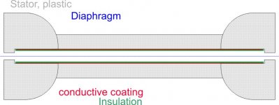
Jesper, I wouldn´t cast the stator in metal, but just metallize the stator surface toward the membrane side. Thinking of using conductive ink (maybe printing) or glueing on metall foil. The Q regarding insulation related to the insulation of this conductive layer (with laquer or similar).
You could maybe design the spacers directly (which You interpreted as the "insulation") into the stator, in forming a outer rim into the plastic frame (regarded the tolerances of the rapid prototyping are are low enough).
See pic.
jauu
Calvin
Yes, a conductive coating of the membrane (and low ohmic HV-bias supply to be precise) leads to non-constant Q, non-linear F and THD. A conductive membrane but a high-Ohmic HV Bias-supply lead to a constant amount of charge on the membrane, but uneven distribution over the surface area of the membrane, which also leads to uneven distribution of F and an increase in THD.
Only a high ohmic value coating distributed evenly over he membrane surface guarantees for constant and locally fixed charge. Then F is proportional to Vsignal and THD becomes minimal.
In a symmetrical ESL the membrane would stay centered, because the attracting forces of the two stators upon the membrane would cancel. Would, if everything were theoretically perfect. In praxis, the membrane will be pulled towards one stator, the harder the higher the bias voltage level. Unfortuantely we want and need as much bias as possible, since this immediately effects the efficiency of the panel and efficiency is the mantra of any good ESL.
Most ESL work under the constant charge premise, but there were and there are ESLs with low ohmic membranes. The older Beveridge, APS, Rennwald, Final and the actual Phios (which are Finals under new name but without the burdon of service for broken finalsAll electrostatic transducers have high resistance (constant charge) diaphragm
) and maybe more. The latter two wouldn´t function with high-R membranes, they are true constant voltage ESLs with all the inherent deficiencies, regardless of what their marketing department tries to tell us.Jesper, I wouldn´t cast the stator in metal, but just metallize the stator surface toward the membrane side. Thinking of using conductive ink (maybe printing) or glueing on metall foil. The Q regarding insulation related to the insulation of this conductive layer (with laquer or similar).
You could maybe design the spacers directly (which You interpreted as the "insulation") into the stator, in forming a outer rim into the plastic frame (regarded the tolerances of the rapid prototyping are are low enough).
See pic.
jauu
Calvin
Attachments
Oh - aaarghhh!! - had just replied to you and then it all disappears because the system timed out
.... anyway ... thank you all for replying and not least outlining the force, Q & V relationships in an electrostatic speaker. I now find that I - hopefully - know what I need to know to progress with my design.
@calvin:
It's a very attractive idea which I've actually had myself. Unfortunately, the plastic of the 3D print I ordered from Shapeways is not firm enough so I doubt it would sound well. Also, I don't know what the dielectric coefficient of the plastic is so attaching conductors to the surface probably will influence the sound.
I've also decided to not cast the stators - it'll either be too expensive for me or challenging with the rods being so thin. Instead I will draw circular or oval copper rods and mount them on a similar outer frame.
@godfrey:
Hmmm... so I guess some experimenting with tensioning relative to low frequency response & voltage is necessary. Thanks for mentioning this
Now off to working on the headphone ...
'Best for your day,
Jesper
.... anyway ... thank you all for replying and not least outlining the force, Q & V relationships in an electrostatic speaker. I now find that I - hopefully - know what I need to know to progress with my design.
@calvin:
Jesper, I wouldn´t cast the stator in metal, but just metallize the stator surface toward the membrane side.
It's a very attractive idea which I've actually had myself. Unfortunately, the plastic of the 3D print I ordered from Shapeways is not firm enough so I doubt it would sound well. Also, I don't know what the dielectric coefficient of the plastic is so attaching conductors to the surface probably will influence the sound.
I've also decided to not cast the stators - it'll either be too expensive for me or challenging with the rods being so thin. Instead I will draw circular or oval copper rods and mount them on a similar outer frame.
@godfrey:
If the membrane is centered between the plates, it will be equally strongly attracted to both of them, so the forces cancel.
Interestingly, if it's not centered then the forces don't balance and the membrane is pulled more strongly towards whichever plate it's closer to. So the electrostatic forces act as a kind of anti-spring, partly counteracting the stiffness due to the membrane tension.
Hmmm... so I guess some experimenting with tensioning relative to low frequency response & voltage is necessary. Thanks for mentioning this
Now off to working on the headphone ...
'Best for your day,
Jesper
Hi,
jauu
Calvin
ps. Jesper, a very danish name Btw. How´s the weather on Helgenaes?
The dielectric constant of the stator wouldn´t be of much interest here, since the metallization would face towards the membrane. It´s the insulation layer on the metallization (between the metallization and membrane, as in the sketch) that would influence on sound and this could be a PU-laquer or similar. The cast or printed frame has to fulfill mechanical requirements in first place and to insure electrical safety by sufficiently large dimensions.Also, I don't know what the dielectric coefficient of the plastic is so attaching conductors to the surface probably will influence the sound.
jauu
Calvin
ps. Jesper, a very danish name
Btw. How´s the weather on Helgenaes?jauu Calvin,
So you know of Helgenæs Actually, today the weather is mostly overcast & right now it's raining, temperatures are about 18 degrees. Although I'm not on Helgenæs I'm only a few kilometers from there so probably more or less the same weather there ...
To me it's a suitable day for "projects" ...
Regarding insulation on cables or other items my experiences are that most all materials laid outside a conductor influences the sound. I used to work with TARA Labs cables here in Denmark and was fortunate enough to own a couple of their The One cable sets. Those were good, however, the cables I mostly liked were uninsulated ones, akin to Tara Labs' The Zero. See e.g. here (at the bottom there's a description of their vacuum design):
TARA Labs The Zero interconnect | Stereophile.com
So, without entering into a discussion on the sound of cables (one of audio's many never-ending discussions in my experience...) I tend to be very cautious of putting materials close to the conductors - with or without an electric field across the material (if that is what you were thinking about?).
This also means that although I'd really like to make these stators in a firmer plastic - my aesthetic sense really likes them - I hesitate to do so because I reckon that the metallization onto the plastic may influence the sound....
To that end: Any of you know of a zero-dielectric coefficient plastic to metal glue that's absolutely enviromentally sound as well
Greetings &
Jesper
So you know of Helgenæs
Actually, today the weather is mostly overcast & right now it's raining, temperatures are about 18 degrees. Although I'm not on Helgenæs I'm only a few kilometers from there so probably more or less the same weather there ... To me it's a suitable day for "projects" ...
Regarding insulation on cables or other items my experiences are that most all materials laid outside a conductor influences the sound. I used to work with TARA Labs cables here in Denmark and was fortunate enough to own a couple of their The One cable sets. Those were good, however, the cables I mostly liked were uninsulated ones, akin to Tara Labs' The Zero. See e.g. here (at the bottom there's a description of their vacuum design):
TARA Labs The Zero interconnect | Stereophile.com
So, without entering into a discussion on the sound of cables (one of audio's many never-ending discussions in my experience...) I tend to be very cautious of putting materials close to the conductors - with or without an electric field across the material (if that is what you were thinking about?).
This also means that although I'd really like to make these stators in a firmer plastic - my aesthetic sense really likes them - I hesitate to do so because I reckon that the metallization onto the plastic may influence the sound....
To that end: Any of you know of a zero-dielectric coefficient plastic to metal glue that's absolutely enviromentally sound as well
Greetings &
Jesper
You could cover your frames with aluminium duct taped and form it through slots as I have done here,
http://www.diyaudio.com/forums/planars-exotics/158115-material-esl-2.html#post2076459
and then coat it with some clear spray acrylic.
I used a bath of sodium hydroxide to etch away the unwanted left over edges in the holes after masking the top surface.
I used a bias of +500v on these.
jer
http://www.diyaudio.com/forums/planars-exotics/158115-material-esl-2.html#post2076459
and then coat it with some clear spray acrylic.
I used a bath of sodium hydroxide to etch away the unwanted left over edges in the holes after masking the top surface.
I used a bias of +500v on these.
jer
Hi,
I´m not sure if You understood correctly what I meant with metallization and insulation. The optics of the stator frame wouldn´t change at all, but safety issues would be greatly reduced against a fullmetal stator. Its just so that the ´function-side´of the stator towards the mebrane would need metallization. The bulk plastik would face towards the head/ear and functions as safety insulation. The metallization would in theory not even need an insulation, if the membrane coating would be of very high resistivity and if the ESL capsule were symmetric. In this case the voltage differential between membrane and stator reduces the closer both approach each other. At distance 0 (contact) the voltage differential would become 0 also, hence no flashover.
Still though a stator insulation towards the membrane is fully recommended. With a SE-ESL, featuring a highly conductive membrane, insulation is not an option but an obligation.
There´s a chance that the stator plastic influences on the electrostatic field and as such influences on sonics, because it functions similar to a ´conductor´ for the electrostatic field. But for a) the dielectric constant is low (bad ´conductor´) and b) is it orientated away from the sound-generating field. The influence is therefore very small, insignificant.
The effects on sonics that follow the decision of using a single stator design, are much greater and they are generally negative effects.
I´d suggest that You get a working -and I mean safe working- symmetrical ESL capsule going and get some basic experience before thinking of certain details which may even seem plausible at first glance, but aren´t.
jauu
Calvin
Yeah, I know Helgenaes. Made holidays there a couple of years as a youngster. Saw my first Rega planar 3 in a shop in Aarhus.
Last edited:
Here is another interesting thread on this topic with a lot of useful construction details:
http://www.diyaudio.com/forums/headphone-systems/132573-has-anybody-made-els-headphone.html
http://www.diyaudio.com/forums/headphone-systems/132573-has-anybody-made-els-headphone.html
Hello!
I haven't been back here for a while. It's always nice to see somebody interested in making electrostatic headphones.
@ Calvin: Have you any progress with those headphone parts I sent you years ago?
@ Gentlevoice: The best and economical material for making stators and spacers, IMO, is PCB. They come in many thicknesses, and can be cut and drilled easily.
Wachara C.
Hey all,
Pleased to read your writings & suggestions And good to see you come around Wachara - I've been reading the thread you started some time ago on EL headphones quite some - very interesting indeed It had/has many sources of inspiration - to me not least your Orpheus shape stators and Phil47's ideas and suggestions.
@calvin:
Hi Calvin, I'm not quite sure I understand what you mean in the above sentences. How can the differential be zero with the membrane polarized to maybe 500 volts? Wouldn't there be the risk of an accidental blow of wind making the membrane touch the stator(s)?
Regarding my comments in the previous post I (hope) I understood what you meant. On the other hand my point was that everything close to a conductor "sounds" - more or less and even if there's no electric field to make the electrons go in the direction of the insulation - so not having anything other than the stator/conductor is preferred to me. And, yes, I'll do a first version which I can learn from.
@geraldfryjr: Hey jer. Thank you also for suggesting & linking. I've taken a look at your link & it looks interesting - yet my approach is somewhat different - but thanks again for posting
@Wachara: Hi Wachara. Appreciate your input, yet in the first round I'd like to more or less go with what Philippe Hiraga suggested in the posts he made in the thread you started. Round or oval wires and a design that makes the air flow "smooth". But I'll keep your suggestion in mind
Greetings to you all,
Jesper
Pleased to read your writings & suggestions
And good to see you come around Wachara - I've been reading the thread you started some time ago on EL headphones quite some - very interesting indeed It had/has many sources of inspiration - to me not least your Orpheus shape stators and Phil47's ideas and suggestions. @calvin:
The metallization would in theory not even need an insulation, if the membrane coating would be of very high resistivity and if the ESL capsule were symmetric. In this case the voltage differential between membrane and stator reduces the closer both approach each other. At distance 0 (contact) the voltage differential would become 0 also, hence no flashover.
Hi Calvin, I'm not quite sure I understand what you mean in the above sentences. How can the differential be zero with the membrane polarized to maybe 500 volts? Wouldn't there be the risk of an accidental blow of wind making the membrane touch the stator(s)?
Regarding my comments in the previous post I (hope) I understood what you meant. On the other hand my point was that everything close to a conductor "sounds" - more or less and even if there's no electric field to make the electrons go in the direction of the insulation - so not having anything other than the stator/conductor is preferred to me. And, yes, I'll do a first version which I can learn from.
@geraldfryjr: Hey jer. Thank you also for suggesting & linking. I've taken a look at your link & it looks interesting - yet my approach is somewhat different - but thanks again for posting
@Wachara: Hi Wachara. Appreciate your input, yet in the first round I'd like to more or less go with what Philippe Hiraga suggested in the posts he made in the thread you started. Round or oval wires and a design that makes the air flow "smooth". But I'll keep your suggestion in mind
Greetings to you all,
Jesper

Hi again,
Still in the process of doing the headphones as a question came up which I hope one of you may just know about:
Suppose I design the electrostatic headphone to have spacers of 0.6 mm between the membrane and the stators and a membrane area of about 50 cm2 do you know what the current requirements for the headphone amp will be (I don't play loud and aim at a 50 Vpp maximum output level)?
Regards from autumn Denmark,
Jesper
- Status
- This old topic is closed. If you want to reopen this topic, contact a moderator using the "Report Post" button.
- Home
- Amplifiers
- Headphone Systems
- Single Stator Electrostatic Headphone - issues?