I'm thinking of getting this amplifier:
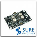
2 X 150 mW Class-AB Headphone Amplifier Board ?LM4881 | eBay
Most kits and ready to go amps that I see here are $30+. The specs for this one look quite decent: 10 dB gain, 11 microvolts noise floor, 0.2% THD etc. I'm thinking of using a 7809 as power supply and a simple wooden enclosure. They're for use with an M-audio AV 40, which has 10 Ohm output impedance at 1000 Hz and 150 Ohm @ 40 Hz.
What do you guys think about it? Can't find any results on this forum when searching for 'LM4881'
Attachments
They're for use with an M-audio AV 40, which has 10 Ohm output impedance at 1000 Hz and 150 Ohm @ 40 Hz.
The AV-40 desktop speakers have an amplifier built in... are you disconnecting the internal amplifier so you can feed the speakers directly with an external amplifier? I did that with my AV-30's and I use this Sure digital amplifier : 2*15W TA2024C Tripath Digital Class-D Amp + 12V adapter | eBay. 150mW wouldn't be anywhere near enough power output for the AV-40s speakers. They are 4 ohm.
M-AUDIO - M-Audio® AV 40 - Monitor Speakers for Professional-Quality Media Creation
Last edited:
...or it just occurred to me you might be asking about feeding that LM4881 headphone amp from the headphone jack on the AV-40? That would probably work if you are using low impedance headphones, but make sure you have a large coupling capacitor between the output and your headphones, either on-board or off, since the power supply is single ended.
Here are some good comments from AMB about that chip in an old post on H-F:
alternative to LM4881???
Here are some good comments from AMB about that chip in an old post on H-F:
alternative to LM4881???
Last edited:
Thanks for your input. I indeed intend to use it with headphones. I had to look up what single ended means for the design - it looks like the board already has capacitors on the headphone jacks, as there are 4 470uF caps on board, so that should be OK. There's not a schematic or even a block diagram to be seen though, so maybe these are just for the power supply? I think the concerns about the chip that AMB comments on about voltage swing and the output capacitors may explain why this chip isn't more popular.
Still leaves a lot of questions open, like:
Why is the board specced for 8-24V operation when the chip is 6V max, and there's no regulator to be seen?
Why is there 1 DIP-switch for controlling gain, when the datasheet shows you need to adjust 2 resistors?
I ordered one, so I'll get back on that when it arrives
Yeah I noticed that voltage discrepency. Sure must be including a regulator chip or DC-DC converter chip. It might be that chip with the three legs on one side and the tab on the other, near the power input, on the photos of the board they've posted.
The data sheet for the LM4881 is kind of technical but worth the read-through, especially the section on page 11 "selection of input and output capacitor size":
http://www.ti.com/general/docs/lit/getliterature.tsp?genericPartNumber=lm4881&fileType=pdf
470uF is on the small side for an output coupling capacitor feeding a low impedance. It forms a filter than will roll off low frequencies. But from the data sheet they know that in their capacitor recomendations, it says, and they are essentially sacrificing frequencies below 150Hz to keep the size of the caps down.
For just $6 that board is certainly worth getting just to mess around with!
It arrived today! The board was packaged in a little sturdy cardboard box, which came in an envelope. There are 4 470uF caps, one for filtering the input of the LM317 voltage regulator(5.5 volts), one for filtering the output, and two for decoupling the output of the power amp. The sound is very clean, and has plenty of bass and can go pretty loud.
However, the noise floor of the LM4881 from the datasheet is 20uV at all frequencies. This is 93 dB below 1V, with a headphone that has a sensitivity of 112 dB/v @ 1 Khz(from the datasheet of the Sennheiser HD555) this should give 112-93=20dB of noise, which indeed is plainly audible When playing music as soft volumes, the noise is audible in the background. This noise is audible even when shorting both the audio inputs to ground and unplugging the PSU so that the chip runs off the 940uF caps as well. It goes up when changing the gain from 9 dB to 16 dB with the DIP-switch as well, so maybe lowering the gain would help? I'm thinking of lowering the resistor that gives feedback. It's now a 10K resistor. Lowering the resistance to 100 Ohm should reduce the gain and the noise, right?
The power supply seems to be important: I tried 2 switching power supplies, but that only work with an mp3 player, as connecting it to my (ungrounded) M-audio AV-40's or my grounded PC creates some kind of ground loop with lots of 50Hz and even more harmonics. The grounds are connected, so what could be the issue here? I'm beginning to understand why people use rechargeables for their headphone amp :/ A benchtop power supply with a 16V 5A transformer works fine though.
@powerflux: AFAIK harmonic distortion is harmonics, and that's what separates a sinus from the sound of an instrument, so it's pretty benign. Levels below 1% should be inaudible. You're right about it the overall performance though :/
@agdr: you were right! It's a lm317K.
According to the datasheet, the dropoff in low frequencies is only -3 dB at 20 Hz with a 32 Ohm load, which isn't too bad. The input capacitor is, measured with a Fluke multimeter, 15uF, so that should drop the 20 Hz band by only >0.1 dB as well.
However, the noise floor of the LM4881 from the datasheet is 20uV at all frequencies. This is 93 dB below 1V, with a headphone that has a sensitivity of 112 dB/v @ 1 Khz(from the datasheet of the Sennheiser HD555) this should give 112-93=20dB of noise, which indeed is plainly audible
When playing music as soft volumes, the noise is audible in the background. This noise is audible even when shorting both the audio inputs to ground and unplugging the PSU so that the chip runs off the 940uF caps as well. It goes up when changing the gain from 9 dB to 16 dB with the DIP-switch as well, so maybe lowering the gain would help? I'm thinking of lowering the resistor that gives feedback. It's now a 10K resistor. Lowering the resistance to 100 Ohm should reduce the gain and the noise, right?The power supply seems to be important: I tried 2 switching power supplies, but that only work with an mp3 player, as connecting it to my (ungrounded) M-audio AV-40's or my grounded PC creates some kind of ground loop with lots of 50Hz and even more harmonics. The grounds are connected, so what could be the issue here? I'm beginning to understand why people use rechargeables for their headphone amp :/ A benchtop power supply with a 16V 5A transformer works fine though.
@powerflux: AFAIK harmonic distortion is harmonics, and that's what separates a sinus from the sound of an instrument, so it's pretty benign. Levels below 1% should be inaudible. You're right about it the overall performance though :/
@agdr: you were right! It's a lm317K.
According to the datasheet, the dropoff in low frequencies is only -3 dB at 20 Hz with a 32 Ohm load, which isn't too bad. The input capacitor is, measured with a Fluke multimeter, 15uF, so that should drop the 20 Hz band by only >0.1 dB as well.
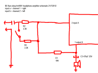
Don't like the look of that feedback loop, surely the input impedance is going to be very low indeed (3.3-1.65K). If I were you I wouldn't use that board for any real listening at all and build a proper headphone amplifier. For a dedicated headphone amp 0.2% THD is a bit of a joke and you're going to get some serious muddying at higher volume levels with that thing.
It's a nice toy for $6 but doesn't have any real place in any decent audio setup and looks like it has quite a few design flaws, I'd build a CMOY with an OPA2134 for something cheap and simple with excellent performance.
It's a nice toy for $6 but doesn't have any real place in any decent audio setup and looks like it has quite a few design flaws, I'd build a CMOY with an OPA2134 for something cheap and simple with excellent performance.
However, the noise floor of the LM4881 from the datasheet is 20uV at all frequencies.
Interesting that regulator turned out to be a LM317! That will be slightly less noisy, if the adjust pin is capacitor bypased, than a fixed voltage regulator. Lowering the voltage gain on the LM4881 board will most likely help a bit with the noise.
I would have to agree with the other posters though that the LM4881 isn't really anywhere near a high end chip. That is a fun project board and gets the job done in a boom box "blaster" kind of sense, but you can do a lot better for a bit more money. Take a look at the O2 project, for one. The noise floor, measured on good equipment, is about -112dB:
NwAvGuy: O2 Headphone Amp (search in the article for "O2 NOISE")
http://www.diyaudio.com/forums/headphone-systems/193977-objective2-o2-headphone-amp-diy-project.html
The noise is still there even with a gain of 1, it's just lower in volume
A O2 isn't an option, as it's $30 instead of $6 and too much work for probably zero audible difference compared to a CMOY, judging by nwavguy's eBay CMOY review. I'll be making a CMOY with a cheap burr-brown on breadboard, for a component cost (without a potentiometer) of even lower than $6
A O2 isn't an option, as it's $30 instead of $6 and too much work for probably zero audible difference compared to a CMOY, judging by nwavguy's eBay CMOY review. I'll be making a CMOY with a cheap burr-brown on breadboard, for a component cost (without a potentiometer) of even lower than $6
- Status
- This old topic is closed. If you want to reopen this topic, contact a moderator using the "Report Post" button.
- Home
- Amplifiers
- Headphone Systems
- $6 headphone amplifier from ebay