Hi guys posting for my second time,
Attached is an amp im trying to modify to my needs, its rated for 5v but I'm needing it for 12V, i have minimal understanding in this area so any help would be great...
The Opa! Amp - iPod Amp for Aux-In
Basically i want to simplify the circuit to have a input 3.5mm headphone jack (including bypass caps) to the Opa amp (Opa2227) then a output 3.5mm headphone jack.
Again it needs to be used with a 12v power source.
Thanks in advance guys!
Luke
Hi,
The OPA2227 in this design can be powered by 12V, no problem (anything from 5 to 36V DC will work). You will need coupling caps and you will need to bias the input to ~6VDC and set the gain. That's pretty much it...
To get decent performance make sure the gain setting resistors are not to large (10K range should do nicely), and make sure you filter the DC supply with a LC filter.
Thanks Mark,
Thankyou for confirming the 12V issue,
As ive said i have little to no experience in circuits, could you possibly quickly make a schematic for what i need. i have no idea. unsure on where to put the LC filter and all that.
Appreciate the help and i know im asking alot!
Thanks again,
Luke
Thankyou for confirming the 12V issue,
As ive said i have little to no experience in circuits, could you possibly quickly make a schematic for what i need. i have no idea. unsure on where to put the LC filter and all that.
Appreciate the help and i know im asking alot!
Thanks again,
Luke
Can't really make a drawing right now, don't have the tools. But let me try to explain.
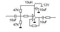
An LC filter is simply a coil and a capacitor, coil in series with the + power supply of the opamp and from the same pin of the opamp a capacitor to ground. This should clean up your power supply. A good starting point would be something like 10uH + 10uF.
The coupling caps are in the signal path (your audio "+" pins) use something like 10uF. Both on the input and the output!
The biasing is done with a voltage divider (2 resistors in series from + power supply to ground), use 2 resistors of 47K for this.
The gain is set with the 2 remaining resistors.
Edit: made a paint drawing, hope that helps..
Attachments
Last edited:
The datasheet with pinouts is available here: http://www.ti.com/lit/ds/symlink/opa2227.pdf
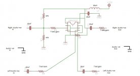
For a 2 channel version just build the circuit 2 times, you will only need one OPA2227 (2 opamps inside)
For a 2 channel version just build the circuit 2 times, you will only need one OPA2227 (2 opamps inside)
Ok im trying to do a schematic at the moment but i cant find an opa2227 chip,
Im trying to make this amp as a part of another mod (LS1GTO.com Forums - View Single Post - AUX input on a factory stereo - my way)
Trying to cut in aux audio but the mod above requires the input device to be turned up high and the headunit itself turned up also, so the idea is to place this opa amp in between the above mod (LS1GTO.com Forums - View Single Post - AUX input on a factory stereo - my way) to eliminate that problem and improve audio quality!
If you get a chance could you help me find the part for eagle cad or help design the idea, id even consider paying you if it all works out")
Thanks for the help!
Im trying to make this amp as a part of another mod (LS1GTO.com Forums - View Single Post - AUX input on a factory stereo - my way)
Trying to cut in aux audio but the mod above requires the input device to be turned up high and the headunit itself turned up also, so the idea is to place this opa amp in between the above mod (LS1GTO.com Forums - View Single Post - AUX input on a factory stereo - my way) to eliminate that problem and improve audio quality!
If you get a chance could you help me find the part for eagle cad or help design the idea, id even consider paying you if it all works out
Thanks for the help!
If you use a program like Eagle for your layout there should be a generic footprint that fits the OPA (DIL8 or something like that). Professionally I used Altium designer, never used Eagle..
If you find the OPA2227 hard to find you can always consider a different opamp for this application. There are many possible options but a few that come to mind are the OPA2134 and the NE5532. Basically any decent quality opamp which is unity gain stable should be able to satisfy your needs.
On a side note: do you know how much gain you need? you will need to figure this out before you build the amp (the resistors set the gain).
I am always willing to help and comment on your layouts, but don't have the time to do it all for you. I also have some projects going on myself
Heres what ive done in eagle let me know where im going wrong
unsure of R4 resistance also
Not much that make sense there, unfortunately.
Start with this circuit:
http://tangentsoft.net/audio/cmoy-tutorial/misc/cmoy-tangent-sch.pdf
Or this one that shows the pin-outs of the chip:
CMoy Headphone Amplifier
In your case there would be only one 12 V supply instead of the two 9 V batteries. So read "+6 V" and "-6 V" where +9 V and -9 V is shown.
Note that the circuit in post 4 does not have any gain. That circuit will also push any power supply noise into the amplifier.
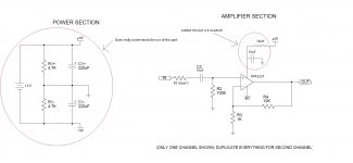
The part on the left is a simple way to use any op-amp with a single power supply. Note that the 3 ground symbols on the schematic are not really ground (virtual-ground) and should only be tied to each other and nothing else!
Figure 2 here shows another way:
Analog Devices: Analog Dialogue: Avoiding Op-Amp Instability Problems In Single-Supply Applications
(The 'OPA amp' in your first link looks like a really bad design BTW.)
To be safe add a capacitor on the output of the circuit, as per post 4, in case the connection on the radio side is DC connected. 1 to 10 uF should be OK. Add 1 Mohm drain resistors on input to virtual-ground and output to virtual-ground to prevent clicks when you plug/unplug the input or output.
Gain of the circuit is R4/R3+1 = 11 as shown. Change R3 to suit your needs.
Take out R1 or use a volume control potentiometer in this position if needed.
Try it without the power filter L and C. The two C1 capacitors already do some filtering.
Be careful where you take the 12 V power supply from. The 0 V (-6 V) will be part of the signal, common to your circuit and the radio and needs to be 'clean' relative to the radio's ground. Also do not tinker with a car's electrical system if you do not know what you are doing. Blown fuses best case, car on fire worst case...
Last edited:
Ok, so ill be needing this circuit to run off the cars headunit supply of 12v
ill add the drain resistors to the schematic...
I now understand the Gain and will replace the resistor i assumed was gain with the drain resistor as i said above...
What else will i need to change?
Ps. I will be doing bench tests before putting this in a car so wont have any problems with cars on fire lol
ill add the drain resistors to the schematic...
I now understand the Gain
and will replace the resistor i assumed was gain with the drain resistor as i said above...What else will i need to change?
Ps. I will be doing bench tests before putting this in a car so wont have any problems with cars on fire lol
mmm, I made a mistake in my drawing, sorry for putting you on the wrong track. That's what happens when you make a quick paint drawing..
Anyway the coil and capacitor are there to filter the power supply. I wouldn't leave them out as car supplies are usually very noisy. For the first bench tests with a lab power supply you don't need them.
Anyway the coil and capacitor are there to filter the power supply. I wouldn't leave them out as car supplies are usually very noisy. For the first bench tests with a lab power supply you don't need them.
Any Feedback guys?
Try it!
Some comments:
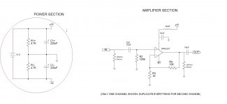
-The power filtering has to go with the power input.
In other words, put the inductor in series with the 12 V supply (on the positive side). The 10 uF is unnecessary, there are already two 220 uF in series (so effectively 110 uF) in the position that it would go. You can add 100 nF to 1 uF capacitors directly at the chip across the -6V to GND and + 6V to GND.
-The 1 Mohm drain resistor has to go on the other side of the output capacitor. Also not tied to amplifier ground, but to radio ground, which may be your -6 V.
-1 uF is plenty for C2, and possibly also for the output C.
- Status
- This old topic is closed. If you want to reopen this topic, contact a moderator using the "Report Post" button.
- Home
- Amplifiers
- Headphone Systems
- OPA AMP