Hello,
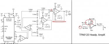
I am building a custom designed DAC that, for what concerns this discussion, follows quite closely the reference PCM63 design (see attached image). I want to integrate it with a TPA6120 headphone amplifier.
I have a major doubt on where to put the volume potentiometer (see the 4 red circles):
(i) before the final dac buffer?
(ii) in its loop (altering its unity gain)?
(iii) after it (before entering the TPA6120)?
(iv) in the tpa6120 loop?
Any help would be really appreciated.
Thanks,
Primiano
I am building a custom designed DAC that, for what concerns this discussion, follows quite closely the reference PCM63 design (see attached image). I want to integrate it with a TPA6120 headphone amplifier.
I have a major doubt on where to put the volume potentiometer (see the 4 red circles):
An externally hosted image should be here but it was not working when we last tested it.
(i) before the final dac buffer?
(ii) in its loop (altering its unity gain)?
(iii) after it (before entering the TPA6120)?
(iv) in the tpa6120 loop?
Any help would be really appreciated.
Thanks,
Primiano
Last edited:
 Your image link is bad, it does not go anywhere (404)
I can't see the link either, but a google search shows that the website exists, it's just down.
Either way, you do not want to put the volume control inside the feedback loop of any part of the circuit, especially not of the TPA6120, which is current feedback and very fast and quite prone to instability.
You need an I/V converter after the PCM63 and the TPA6120 needs to be driven from a low source impedance. If you place a potentiometer after the I/V converter then you need an opamp following it before the TPA6120. You do not want the pot after the TPA. So really what you want is
PCM63>I/V>Pot>Buffer opamp>TPA6120.
In my set up I go
PCM1792>I/V>CS3318>TPA6120.
Seconded.So really what you want is
PCM63>I/V>Pot>Buffer opamp>TPA6120.
The resistor and the cap before the red circle form a potential divider that acts as a low pass to filter the signal coming out of the DAC. If you place another resistor (the pots trace) in parallel with the cap then at DC/low frequencies this will act as a further divider in combination with the 1.33k resistor to lower the overall output.
In other words at low frequencies, where the caps impedance is very high, all of the signal normally enters the opamp. If you were to use a 1.33k pot, even with the wiper in the maximum position, you would end up with half of the signal entering the opamp compared to if the pot wasn't there. In the maximum position the 1.33k pot would still form a potential divider with the 1.33k resistor, cutting the signal at the opamps input in half.
Using a larger value pot obviously reduces this effect. With a 50k pot, if the maximum signal amplitude would be normally be ~2.1Vrms, it would now be reduced to ~2.07Vrms. This isn't going to be a problem. You can use lower value pots if you want to but you might need to increase the gain @ the TPA6120 if it wont go loud enough (I highly doubt that this will be the case).
Ehm... Why load futher the IV/filter output, won't FET opamp be the best option to use there (call it buffer), throw a pot between THS and TPA (TPA will benefit from additional "buffer" or composite-opamp thing). Keep the DAC's buffer powerful, keep pot's impedance low (10k)...
Don't forget that the pot should be placed at front panel, with long wires involved. Highish output impedance of DAC's filter plus longish wires = pretty awesome noise-picking antenna.
Don't forget that the pot should be placed at front panel, with long wires involved. Highish output impedance of DAC's filter plus longish wires = pretty awesome noise-picking antenna.
5th element: I didn't notice that, but yep it's true, the pot trace in that position seems to be likely to change the filter response. At this point the (iii) seems the most reasonable one (the 3rd red circle, before the TPA).
I've not completely understood the point about (another?) buffer?
So you're telling that if I put even a 10k pot after all the dac opamps, before the TPA, that 10k impedance signal won't be enough for driving the TPA?
Which is the sink impedance for the TPA, could not find it into its datasheet.
s3tup: If I understand correctly you're suggesting to "re-buffer" the pot output before entering the TPA? Or entering direct with 10k pot?
As regards the wiring issue, I kept that in mind, but I was mostly oriented on putting the pot directly on the pcb (so closest possible to the source and sink) and use a mechanical remote shaft, something like this:
Thanks all for your precious advices,
Cheers
I've not completely understood the point about (another?) buffer?
So you're telling that if I put even a 10k pot after all the dac opamps, before the TPA, that 10k impedance signal won't be enough for driving the TPA?
Which is the sink impedance for the TPA, could not find it into its datasheet.
s3tup: If I understand correctly you're suggesting to "re-buffer" the pot output before entering the TPA? Or entering direct with 10k pot?
As regards the wiring issue, I kept that in mind, but I was mostly oriented on putting the pot directly on the pcb (so closest possible to the source and sink) and use a mechanical remote shaft, something like this:
An externally hosted image should be here but it was not working when we last tested it.
Thanks all for your precious advices,
Cheers
any chance of dropping the FDNR filter and going for superior performance multiple feedback filters with low output Z
part of the FNDR filter "quality" depends in part on input common mode impedance linearity - a rarely speced op amp parameter which is usually worse in fet input op amps
and I would add a filter pole to the I/V op amp with a feedback C to reduce its slew rate demand/distortion
I would mark its absence in the PMC63 datasheet app circuit a fail
the TPA6120 has fairly high noninverting input Z but somewhat high bias current so offset V can be a issue with higher input Z like volume pots at midpoint
more specs for the TPA6120 can be found in its DSL driver datasheet - THS6012
I think the best use of the TPA6120 is as the ouptut stage/current buffer in a multiloop composite amplifier with a "good", "audio" op amp input - like OPA627, or more recent parts aimed at replacing it, wrapping a feedback loop around the TPA6120
- Status
- This old topic is closed. If you want to reopen this topic, contact a moderator using the "Report Post" button.
- Home
- Amplifiers
- Headphone Systems
- Single ended DAC + TPA6120, where to put the pot?