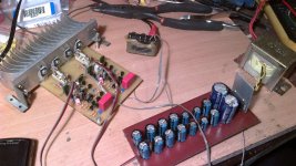
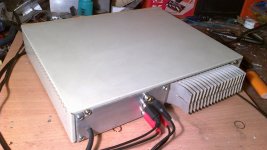
This is one of two head-amplifiers that i have built in a same time. I have got the scheme somewhere from the internet with familiar signature of dr.Borivoje Jagodić so i have saved it in my computer.
I don´t have any experience in headphone amplifiers or in a headphone themselves,but the difference between say usuall headphone output from commercial devices is huge. I beleive that large part of it´s directivity owes to a direct conection with speakers,without any resistors between the amplifier it self and headphones.
Headphones are Sony MDR-CD480 ,they are not hi-fi or hi-end but for me they are still a step forward from what i have had before.
I will put a schematics of it if the boraomega agrees,hope he will notice this thread. The pcb is something that each of us will have to ask from him directly,that is the way i got them.
Has someone else did this headphone amplifier too,any sound impressions?
(the transformer from the amplifier will be changed from 2x11Vac EI to a 2x18Vac toroid,to get smaller magnetic dissipation inside an inclosure and the right power voltage of +/-24Vdc,now it is about +/-16Vdc)
Attachments
Indeed, it is output resistance that may have a significant influence on sound. It forms a voltage divider with the generally non-constant headphone impedance.I don´t have any experience in headphone amplifiers or in a headphone themselves,but the difference between say usuall headphone output from commercial devices is huge. I beleive that large part of it´s directivity owes to a direct conection with speakers,without any resistors between the amplifier it self and headphones.
A few examples, going from non-critical to very fussy:
An externally hosted image should be here but it was not working when we last tested it.
The vast majority of headphones is built to sound best with a low-impedance output, though the occasional exception does exist.
Output resistance in commercial integrated amplifiers and receivers commonly ranges from 330 to 470 ohms, while dedicated headphone amps tend to exhibit no more than a about 100 ohms at best (values around 10 ohms to <1 ohm are common).
STACCATO
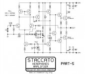
I have received an information that the right name of this amplifier is STACCATO with two " C " ,so i would like to ask the moderators of this forum please to change the title,or to point me how to do it myself.
.
.
By the way,here is the schematic but for pcb and layout you should ask Borivoje Jagodic - boraomega himself.
.
.
.
Thanks for this interesting text sgrossklass!")
I have received an information that the right name of this amplifier is STACCATO with two " C " ,so i would like to ask the moderators of this forum please to change the title,or to point me how to do it myself.
.
.
By the way,here is the schematic but for pcb and layout you should ask Borivoje Jagodic - boraomega himself.
.
.
.
Thanks for this interesting text sgrossklass!
Attachments
Last edited:
That's pretty much a classic "Blameless" topology with a Darlington VAS. As shown, it is best suited for driving higher-impedance or insensitive headphones due to ~21 dB gain.
There are several refinements I could think of:
1. There is no provision of RF filtering at the input (or output), potentially giving problems in areas of high radio/TV fieldstrengths.
2. Given the decent input stage current, feedback resistors (22k/2k2) could easily be chosen a factor of 2 or 3 lower for lowest residual noise.
3. The connection to feedback between the two 820 ohm resistors actually is not beneficial and should be removed for best performance with real-life loads.
4. One could get a little more fancy with part choices, e.g. use transistors with higher Early voltage and lower Cob for VAS and current sources, and ones with more constant beta for drivers.
5. For applications with considerably reduced gain, best replace 2k7 in the VAS with an appropriately sized current source for much reduced common-mode distortion.
6. A tail-driven cascode in the LTP could be used to reduce nonlinear input capacitance.
Your first sentence was almost the same as boraomega's in a feturn mail when i asked him if i could post the schematic here. He actually said that someone will imediately tell me that it is pretty basic topology,but i haven't hoped for such detailed upgrade suggestions! When i read some more (and more) books i will better understand these sentences! Thank you wery much for posting here!
What would be actions of preventing from radio frequencies in input and output?
When i read some more (and more) books i will better understand these sentences! Thank you wery much for posting here!What would be actions of preventing from radio frequencies in input and output?
You can try the following:What would be actions of preventing from radio frequencies in input and output?
* connect input/output ground to chassis vs. ~10 nF ceramic (so the chassis has a better chance of acting as a Faraday cage)
* 100 pF ceramic to ground directly at each input...
* ... followed by a about 1 kOhm in series and ~220 pF to ground, and maybe another 220R to input transistor base. (If there's a volume pot, that goes before the 220R. If connected by a long cable, that one may need special attention in the form of a common-mode choke.)
* The output tends to be relatively uncritical, as there typically is a Zobel network that keeps RF impedance fairly low anyway (try 47R - 10n or so), and possibly even a series L (with parallel R) when going to the output jack.
These are about the standard precautions for keeping MW and higher out. If you have issues with longwave signals, more drastic measures may be needed.
You can look at the input circuitry of a Kenwood L-1000M power amp to get a glimpse of how a fancier solution might look like.
Another trick that allows larger-value input capacitors is using input bootstrapping at audio frequencies. That's a little advanced though and not recommended for the novice.
Unfortunately just about the only test of effectiveness is using the component in a known harsh RF environment or conducting tests in an EMC measurement chamber ($$$). Of course one can test whether the component is audibly bothered by a mobile phone transmitting or DECT/WLAN, but that's far from comprehensive.
You can also do something against generating unwanted RF emissions within the component itself:
If you have used an ordinary silicon rectifier (or ordinary discrete rectifier diodes), place a 10..100 nF film capacitor in parallel to each diode. Alternatively, use fast recovery types.
A standard, non-bypassed rectifier can be quite a buzzy affair on the AM bands at higher current (esp. because of capacitor charging).
Last edited:
You can try the following:
* connect input/output ground to chassis vs. ~10 nF ceramic (so the chassis has a better chance of acting as a Faraday cage)
* 100 pF ceramic to ground directly at each input...
* ... followed by a about 1 kOhm in series and ~220 pF to ground, and maybe another 220R to input transistor base. (If there's a volume pot, that goes before the 220R. If connected by a long cable, that one may need special attention in the form of a common-mode choke.)
* The output tends to be relatively uncritical, as there typically is a Zobel network that keeps RF impedance fairly low anyway (try 47R - 10n or so), and possibly even a series L (with parallel R) when going to the output jack.
These are about the standard precautions for keeping MW and higher out. If you have issues with longwave signals, more drastic measures may be needed.
You can look at the input circuitry of a Kenwood L-1000M power amp to get a glimpse of how a fancier solution might look like.
Another trick that allows larger-value input capacitors is using input bootstrapping at audio frequencies. That's a little advanced though and not recommended for the novice.
Unfortunately just about the only test of effectiveness is using the component in a known harsh RF environment or conducting tests in an EMC measurement chamber ($$$). Of course one can test whether the component is audibly bothered by a mobile phone transmitting or DECT/WLAN, but that's far from comprehensive.
You can also do something against generating unwanted RF emissions within the component itself:
If you have used an ordinary silicon rectifier (or ordinary discrete rectifier diodes), place a 10..100 nF film capacitor in parallel to each diode. Alternatively, use fast recovery types.
A standard, non-bypassed rectifier can be quite a buzzy affair on the AM bands at higher current (esp. because of capacitor charging).
Thank you so much,i will write this down to a paper and than do it in practise,part by part!
You can try the following:
* connect input/output ground to chassis vs. ~10 nF ceramic (so the chassis has a better chance of acting as a Faraday cage)
* 100 pF ceramic to ground directly at each input...
* ... followed by a about 1 kOhm in series and ~220 pF to ground, and maybe another 220R to input transistor base. (If there's a volume pot, that goes before the 220R. If connected by a long cable, that one may need special attention in the form of a common-mode choke.)
* The output tends to be relatively uncritical, as there typically is a Zobel network that keeps RF impedance fairly low anyway (try 47R - 10n or so), and possibly even a series L (with parallel R) when going to the output jack.
Precautions and compensations is an art. You can make the amp bullet proof and sound like a public address amplifiers.
Musical Fidelity A1 is very popular for it's reputation to go frequently into repair shops. I didn't even want to connect it to my main speakers...
But Boraomega modification to the MFA1 removes many compensation schemes! I think that is cool...
Today it will get a proper 30VA toroid transformer with 2x18Vac secondary voltage, than i'll see how it will behave. Since it has +/- 24V supply,i guess that it wouldn't be so bad idea to put some dc-protection inside. I'm thinking about Elliot Soundwesthost Project 33. Would this be a good idea or not so needed device?
finnished for now...
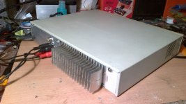
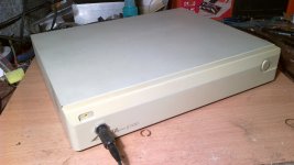
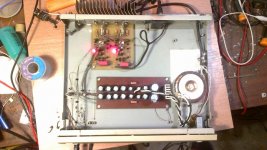
It is finnished at least for now. Today it got his 30VA 2x18Vac toroid transformer and +/-24Vdc supply,quescent current of 70mA and much of the noise that existed before dissapiared. I´d say it is now fully operational amplifier,and it will stay like this i´d say for a long long time.
on a first picture is how it looks like now,
on a second is a temperature of a heatsink,
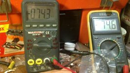
third would be quiscient currents per channel (mV on 1R resistors),
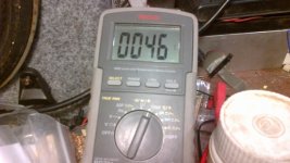
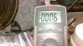
fourth is a dc-offset on one channel and
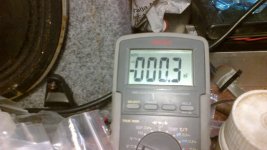
fifth is dc-offset on the other channel. That could be better if i used multiturn trim-pots instead regular. Untill something else comes to my mind (maybe input pot and dc-protection...) this will be it.
It is finnished at least for now. Today it got his 30VA 2x18Vac toroid transformer and +/-24Vdc supply,quescent current of 70mA and much of the noise that existed before dissapiared. I´d say it is now fully operational amplifier,and it will stay like this i´d say for a long long time.
on a first picture is how it looks like now,
on a second is a temperature of a heatsink,
third would be quiscient currents per channel (mV on 1R resistors),
fourth is a dc-offset on one channel and
fifth is dc-offset on the other channel. That could be better if i used multiturn trim-pots instead regular. Untill something else comes to my mind (maybe input pot and dc-protection...) this will be it.
Attachments
Or even better, make it bulletproof and not sound like one, which would generally be preferred. Takes a few more parts, but that shouldn't be much of an issue in DIY.Precautions and compensations is an art. You can make the amp bullet proof and sound like a public address amplifiers.
Funny you should mention PA amps though. This blind listening test found participants unable to distinguish between a fancy expensive setup and another using a basic DVD player and lowly Behringer PA/studio amp. That's the same kind of Behringer amp as measured here (generally decent, though high-frequency distortion isn't quite as low as I'd like and you have to be careful with the gain control setting).
This is not the 70s any more. In any kind of decent PA amp, bad sound is likely to be the result of disturbing fan noise rather than electrical performance.
The first thing I think of with this model is scratchy volume pot - a result of the inverting gain amplifier. It seems to be quite decent once you rip out the preamp and replace it by a conventional one.Musical Fidelity A1 is very popular for it's reputation to go frequently into repair shops. I didn't even want to connect it to my main speakers...
But Boraomega modification to the MFA1 removes many compensation schemes! I think that is cool...
@44250: Protection circuitry certainly would come in handy in case of catastrophic failure. Project 33 seems a little complex though, but I think you can get finished DC protection boards from eBay for not that much money. Or maybe build something with a protection IC like the venerable TA7317.
BTW, a <1 mV DC offset is perfectly fine. I wouldn't be complaining about anything under 10 mV!
Last edited:
Or even better, make it bulletproof and not sound like one, which would generally be preferred. Takes a few more parts, but that shouldn't be much of an issue in DIY.
Audio design is about compromise and trade-off. You can always improve amp sound performance by lowering its safety factor. My point is, you should know what kind of safety factor given by "x" pF of capacitance at certain location, not just add anything that will improve something.
PA amps are designed to be used by careless people. Amps are rented, and the user will turn the volume knob to its full limit. And many speakers will be paralleled to give very low impedance load to the amp.
This is not the 70s any more. In any kind of decent PA amp, bad sound is likely to be the result of disturbing fan noise rather than electrical performance.
You cannot compare good PA amp with bad home amp. Must do it apple to apple.
Funny you should mention PA amps though. This blind listening test found participants unable to distinguish between a fancy expensive setup and another using a basic DVD player and lowly Behringer PA/studio amp.
I strongly believe that if that blind test were conducted in our local high-end audio community, the result would be different.
You don't need to close your eyes or doing meditation to judge sounds
The first thing I think of with this model is scratchy volume pot - a result of the inverting gain amplifier. It seems to be quite decent once you rip out the preamp and replace it by a conventional one.
All old amps use bad opamps. Of course, upgrading the opamp will improve things. But I was talking about Boraomega modification to the core amplifier circuit.
maybe a little late but a different take on "improvements"
Distortion In Power Amplifiers is a good intro to some of the design issues
obviously Self's Amplifier Design books are more complete
the Staccato falls short of "Blameless" in a few places
input degen with higher bias for improved linearity is the mode today for bjt input instead of the undegenerated diff pair biased for "noise optimum" - well described in the above link
the "Buffered VAS" is good but the literal "Darlington" connection of the input ef Q collector to the output of the VAS adds unecessary distortion - return the VAS input Q collector to a AC gnd - either gnd or V-
the "beta enhanced" VAS is a good candidate for two-pole compensation
the output driver Q emitter R shouldn't be connected to the output - lift this junction and the driver bias current becomes more constant - I would also increase the bias current here at least 2x
the feedback DC blocking C AND offset trim is excessive - the input
Q should be matched well enough than you don't need both
for lowest distortion the blocking C should be bipolar and have higher V rating
Last edited:
Dear 44250: Can you send me for Staccato head amp PCB layout, I'll diy this head amp, because I want to compare staccato head amp with clepsidra preamplifier by Dr.Jagodic!
Thanks!
That is something that boraomega should do if he wants to,i also asked him for files.
Distortion In Power Amplifiers is a good intro to some of the design issues
obviously Self's Amplifier Design books are more complete
the Staccato falls short of "Blameless" in a few places
input degen with higher bias for improved linearity is the mode today for bjt input instead of the undegenerated diff pair biased for "noise optimum" - well described in the above link
the "Buffered VAS" is good but the literal "Darlington" connection of the input ef Q collector to the output of the VAS adds unecessary distortion - return the VAS input Q collector to a AC gnd - either gnd or V-
the "beta enhanced" VAS is a good candidate for two-pole compensation
the output driver Q emitter R shouldn't be connected to the output - lift this junction and the driver bias current becomes more constant - I would also increase the bias current here at least 2x
the feedback DC blocking C AND offset trim is excessive - the input
Q should be matched well enough than you don't need both
for lowest distortion the blocking C should be bipolar and have higher V rating
This headphone amplifier has been designed before about thirty years,long time before D.Shelf´s book was written
. I am sure that it is not a problem to boraomega to do compleetly new design knowing things that are relatively new and with newer parts and it´s characteristics. I have built it because i have heard some positive critics about it although it` s designing date. If it is not a d-class,a good design from 70` es - 80´es is a good design today too. What ever people do,there is always some place to make it better,but this one works just fine as it is,and i am glad to have it. Greetings from Serbia! - Status
- This old topic is closed. If you want to reopen this topic, contact a moderator using the "Report Post" button.
- Home
- Amplifiers
- Headphone Systems
- boraomega´s STACATO HeadPhoneAmplifier