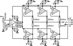
I made my new amp with good parameters. The amplifier is able to provide up to 300 mA output current. The amplifier is based on the idea of increasing the output current by paralleling the buffer amplifiers. I used the following components and parameters:
IC1 - Analog Devices OP27 - precision opamp gives low output offset
IC2/3/4 - Philips NE5532 - good opamp as a buffer - gives ~ 50mA(and low distortion).
Schematic:
Photo of my sample:
Audio interface - E-MU 0202 USB
Thd of amp:
IMD:
IC1 - Analog Devices OP27 - precision opamp gives low output offset
IC2/3/4 - Philips NE5532 - good opamp as a buffer - gives ~ 50mA(and low distortion).
Schematic:
An externally hosted image should be here but it was not working when we last tested it.
Photo of my sample:
An externally hosted image should be here but it was not working when we last tested it.
Audio interface - E-MU 0202 USB
Thd of amp:
An externally hosted image should be here but it was not working when we last tested it.
IMD:
An externally hosted image should be here but it was not working when we last tested it.
I guess these were unloaded measurements? Looks very clean in any case.
50 mA per 5532 seems a little optimistic. According to tests performed by Sijosae, about 35-40 mA is more realistic. Anyway, 6 of them give plenty of output for a headphone amp.
The only choice I'd diagree with is the OP27. It is an old precision op-amp design with bias current cancellation that is optimized for DC rather than AC performance. While the low effective bias current keeps your volume pot crackle-free and saves on a few (cheap) components, Douglas Self notes high levels of common-mode distortion at high frequencies (which is consistent with measurements I've seen lately), along with real-life voltage noise rather being worse than for a 5534. I'd try an LME49710.
That makes me wonder whether the very low specified input bias currents may not actually be real.LME49710/LME49720/LME49740/LM4562 can give bad clicking noise.(in some designs i got this noises)
This lab outlines a simple way of measuring Ib. Should be quick to build. Maybe try it some time?
No need in super fast buffers for sound band frequences.
9v/us can give 1,8Mhz(without distortion) on 5v of out(super ears that hears distorsion over 22000hz? I don't think so).
500V/us;1000V/us;2000V/us - video opamps(need in big output swings and high frequences).
In top audio chips used 3~20V/us(3-20V/us )
"Very high speed opamp needed in for sound " - delusion.
High speed opamp started from 9V/us
High speed opamps have high offset voltage - very bad for sound. - low power headphones can be burned.
I guess these were unloaded measurements? Looks very clean in any case.
Indeed. Show me 16 ohms on the output, then we can discuss.
As an aside, funny how people just take as fact this notion that the problem with op amps re driving headphones is the lack of current output, and the solution is therefore more op amps.
I've never seen a credible justification for that, theoretical or practical.
Why stop at 300 mA after all. If you want output current, a complimentary pair of transistors can do AMPS...
do you understand feedback theory, loop stability?
"speed" can also mean GBW product - critical for Nyquist stability - gets "interesting" when you add amps in series in a loop and ignore added the phase shift
with a loop gain of 3 you have some margin with a unity gain internal compensated input op amp of ~ the same GBW as the 5532, but if you put a 5534 in the input op amp position you would have a marginally stable system without adding compensation components
if someone wanted to use the amp with sensitive IEM then it would be "reasonable" for them to change the amp' gain to unity - then you are courting stability trouble with input op amp even just the same GBW as the 5532
without a warning on acceptable types less informed diyers will see the input op amp as a opportunity for "op amp rolling" - many of the "popular" (but often inappropriate) substitute op amps are too fast for your circuit - have >20 MHz GBW - will likely outright oscillate with the "slow" 5532 "buffer" you show
there is a reason the popular IC buffers have ~100 Mhz corner frequency - so you can mostly ignore the added loop phase shift when using these buffers inside feedback loops of most (earlier op amps anyway - everything is getting faster today) unity gain compensated op amp circuits
"Very high speed opamp needed in for sound " - delusion.
True in general, but his point was that if you make a compound amplifier, with the buffer in the feedback loop, the buffer circuit itself has to have an open loop bandwidth significantly higher than the op amp itself, or risk compromising the stability of the feedback loop.
You built this amp with an 8 MHz op amp as the buffer wrapped up in the feedback loop of a another 8 MHz op amp. Maybe I'm wrong, but that seems like asking for trouble.
Each of those NE5534 chips is running as a unity gain buffer, well over 60 dB feedback ... wrapped up in another 60 dB or thereabouts from the OPA27. That circuit is pretty tightly cranked. Wouldn't take much to send it spinning.
By the way, for unity gain operation you are supposed to use a 22 pF cap on the COMP pins of the NE5534...
(edit: While I was writing this jcx posted his response above - so, yeah, what he said.
") )
)(and another thing: why not just keep the voltage gain stage independent? Like the circuit attached. Good night!)
Attachments
Last edited:
most headphones use TRS 3 pin connector with R,L gnd common
the few TRRS 4-pin headset connectors are used mostly for an extra function - like a microphone
there is a "audiophile" headphone recabling cottage industry that replaces the TRS with 4 indpendent wire/4-pin connectors for "balanced" cable/amp combos
the few TRRS 4-pin headset connectors are used mostly for an extra function - like a microphone
there is a "audiophile" headphone recabling cottage industry that replaces the TRS with 4 indpendent wire/4-pin connectors for "balanced" cable/amp combos
Last edited:
op27 speed - 2,7v/us GBW - 3Mhz on A=3
ne5532 - 9v/us on A=1(buffer)
I checked my circuit on the oscilloscope - the result was very good, with no signs of excitement.
but you can use:
IC1: lm4562
IC2/3/4: lm6172
And you get similar to my results, I'm sure that will be almost no difference.
In this scheme, one can choose the op-amps to your preference.
The scheme is published as an idea how to get the necessary parameters.
And jcx rights IC2/3/4 should be faster(must have bigger GBW) than IC1.
As a rule of thumb, buffer bandwidth >= 3x gain stage bandwidth seems to work well. (Note that gain stage BW = Gain stage GBW / gain.)
Note that output loading may drag down buffer GBW. That I guess is why the classic Apheared-47 circuit (which employs two identical opamps as gain stage and buffer) uses equal current sharing resistors.
Note that output loading may drag down buffer GBW. That I guess is why the classic Apheared-47 circuit (which employs two identical opamps as gain stage and buffer) uses equal current sharing resistors.
- Status
- This old topic is closed. If you want to reopen this topic, contact a moderator using the "Report Post" button.
- Home
- Amplifiers
- Headphone Systems
- DIY headpone amp with ~300mA output