


The TPA6120 has high input bias...you might consider an input buffer.
Don't forget to design your board to use the thermal pad on the underside
of the chip.
Don't forget to design your board to use the thermal pad on the underside
of the chip.
The TPA6120 has high input bias...you might consider an input buffer.
Don't forget to design your board to use the thermal pad on the underside
of the chip.
Thank for your advice.
I'm designing input buffer now.
And for thermal pad, yeah, i drew it when I drew TPA6120A2 footprint(except nearby feedback components).
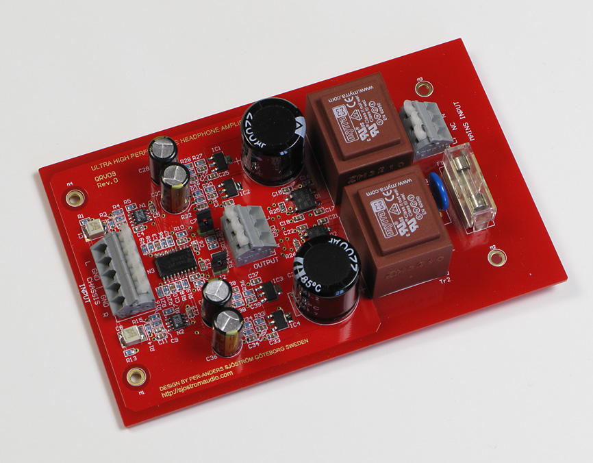
you might look at Peranders TPA6120 project for ideas, pwr pad soldering hints
rather than a independent buffer op amp in front I much prefer a Multiloop topology where a good quality "audio" op amp applies global feedback around the TPA6120 - this improves the performance of both amps in the composite
Walt Jung has written about these multiloop composite amps for audio line driving, check his site, his "Op Amp Applications" book (online at Analog.com)
you might look at Peranders TPA6120 project for ideas, pwr pad soldering hints
rather than a independent buffer op amp in front I much prefer a Multiloop topology where a good quality "audio" op amp applies global feedback around the TPA6120 - this improves the performance of both amps in the composite
Walt Jung has written about these multiloop composite amps for audio line driving, check his site, his "Op Amp Applications" book (online at Analog.com)
Thanks for your advice.
I'm interesting of Peranders TPA6120 project.
Could you please provide me some information about it?
should be enough keywords in my post for search to work
Google
QRV07 Headphone amp
Walt Jung articles, multiloop "audio line drivers" 2nd half of page:
http://waltjung.org/Classic_Articles.html
QRV07 Headphone amp
Walt Jung articles, multiloop "audio line drivers" 2nd half of page:
http://waltjung.org/Classic_Articles.html
This chip was designed to be a line driver,so it's quick and powerful,on the other hand,take care of the PCB designing,chip capacitors and resistors are strongly recognized.
The bias is max 12 uA! Compare the data sheet THS6012, the same chip. 5 kohm feedback may not be good. This is a current feedback amp and the feedback value is very sensitive.The TPA6120 has high input bias...you might consider an input buffer.
Don't forget to design your board to use the thermal pad on the underside
of the chip.
5 kOhm is "over-compensation" - since the current feedback op amp feedback R value ~ determines (inverse) GBW, this higher value slows down the amp, may make it easier to stabilize
12 uA could be too big a input current for noiseless, long life for volume pot wiper, OK if driven from a lower Z source
12 uA could be too big a input current for noiseless, long life for volume pot wiper, OK if driven from a lower Z source
Last edited:

I am doing the same project if you want to work a little together on it. I am using two opa4134 for the first stage into the TPA6120. I am making it according to the Ti PDF information. http://www.ti.com/lit/ds/symlink/tpa6120a2.pdf. But I am using DC CUI regulators for the power input. Running the two 4134 at 9V and TPA at 15V
I am doing the same project if you want to work a little together on it. I am using two opa4134 for the first stage into the TPA6120. I am making it according to the Ti PDF information. http://www.ti.com/lit/ds/symlink/tpa6120a2.pdf. But I am using DC CUI regulators for the power input. Running the two 4134 at 9V and TPA at 15V
- Status
- Not open for further replies.
- Home
- Amplifiers
- Headphone Systems
- I'm designing a TPA6120 based headphone amp, is there anyone can give me some advice