Hello,
I'm working on a small semi-SMD headphone amp that will be run from a single 1200mAh 3.7v Li-ion battery. I've got the charging circuit set (USB charging), but I need higher voltages as well as a negative rail for the opamp (+/-5v or more) referenced at true ground. I thought about using a virtual ground circuit, but it would introduce complications during USB charging. I looked at the LT3471 and it appears to be the perfect chip. Unfortunately, the reference board is 4-layers, and I plan to etch my own, which will be limited to 2 layers. I asked a friend about it, and he said it was feasible on 2-layer, but the EMI would be excessive. Since it's a power supply, is that a big issue? If not, great, but if so, I need a new power supply scheme. It would probably be feasible to use two separate ICs for boosted and inverted outputs, but I can't seem to find any with high efficiency. Perhaps if there's a counterpart to the TPS61085 that produces a negative rail that would work.
Help, suggestions, and ideas welcome. Thanks.
I don't have any answers for you, but I commend you on the project! ") There is sort of a gap there in headphone amp DIY offerings.
There is sort of a gap there in headphone amp DIY offerings.
The mini^3 is a terrific super-small battery-powered DIY headphone amp that uses a virtual ground: The Mini³ Portable Stereo Headphone Amplifier
The O2 is a great battery-powered headphone amp that uses a real ground (two batteries), but is big - twice the size of the mini^3: http://www.diyaudio.com/forums/headphone-systems/193977-objective2-o2-headphone-amp-diy-project.html
I've been hoping someone would whip up the third option, an all-SMD headphone amp that is the small size of the mini^3, using both the top and bottom of the PCB for parts with one or two layers in the middle, and a dual rail dc-dc converter with a single-cell lithium flat pack or cell-phone battery for power. Sounds like you are heading in this general direction.
I wasn't aware of the LT3471 but it sounds like the perfect chip if the sections are isolated. At 1.2Mhz the output should be easy to filter and shouldn't leave any audio band traces. You would want to use a battery management/charge-controller chip with that Li-Ion cell. If you use USB for charging you might want to consider leaving USB 2.0 in the dust specify USB 3.0 right off the bat. That would give you 4x the power budget to work with. I see that many laptops come with USB 3.0 now.
OPC discovered with the Wire headphone amp (not battery powered) that a ground plane in the center dropped the noise floor considerably over ground fill on the top and bottom. If you get really ambitious and find you want a 3rd or 4th layer you might check for interest out on the group buy forum here. There may be others willing to go in on something like that (PCB), which would get the cost down, and would wind up with a much better board than home brew. SMD would leave out a lot of newbie DIY-ers, but there are still a lot of us out there who are comfortable with SMD soldering. The Wire was all SMD and that had huge interest.
Good luck!
There is sort of a gap there in headphone amp DIY offerings.The mini^3 is a terrific super-small battery-powered DIY headphone amp that uses a virtual ground: The Mini³ Portable Stereo Headphone Amplifier
The O2 is a great battery-powered headphone amp that uses a real ground (two batteries), but is big - twice the size of the mini^3: http://www.diyaudio.com/forums/headphone-systems/193977-objective2-o2-headphone-amp-diy-project.html
I've been hoping someone would whip up the third option, an all-SMD headphone amp that is the small size of the mini^3, using both the top and bottom of the PCB for parts with one or two layers in the middle, and a dual rail dc-dc converter with a single-cell lithium flat pack or cell-phone battery for power. Sounds like you are heading in this general direction.
I wasn't aware of the LT3471 but it sounds like the perfect chip if the sections are isolated. At 1.2Mhz the output should be easy to filter and shouldn't leave any audio band traces. You would want to use a battery management/charge-controller chip with that Li-Ion cell. If you use USB for charging you might want to consider leaving USB 2.0 in the dust specify USB 3.0 right off the bat. That would give you 4x the power budget to work with. I see that many laptops come with USB 3.0 now.
OPC discovered with the Wire headphone amp (not battery powered) that a ground plane in the center dropped the noise floor considerably over ground fill on the top and bottom. If you get really ambitious and find you want a 3rd or 4th layer you might check for interest out on the group buy forum here. There may be others willing to go in on something like that (PCB), which would get the cost down, and would wind up with a much better board than home brew. SMD would leave out a lot of newbie DIY-ers, but there are still a lot of us out there who are comfortable with SMD soldering. The Wire was all SMD and that had huge interest.
Good luck!
Last edited:
Hello,
I'm working on a small semi-SMD headphone amp that will be run from a single 1200mAh 3.7v Li-ion battery. I've got the charging circuit set (USB charging), but I need higher voltages as well as a negative rail for the opamp (+/-5v or more) referenced at true ground. I thought about using a virtual ground circuit, but it would introduce complications during USB charging. I looked at the LT3471 and it appears to be the perfect chip. Unfortunately, the reference board is 4-layers, and I plan to etch my own, which will be limited to 2 layers. I asked a friend about it, and he said it was feasible on 2-layer, but the EMI would be excessive. Since it's a power supply, is that a big issue? If not, great, but if so, I need a new power supply scheme. It would probably be feasible to use two separate ICs for boosted and inverted outputs, but I can't seem to find any with high efficiency. Perhaps if there's a counterpart to the TPS61085 that produces a negative rail that would work.
Help, suggestions, and ideas welcome. Thanks.
Hi Spring Halo,
what do you think about these schematic? I was try it to drive my cMoy preamp. And work well. Just replace LM1875 to TDA2050.
Attachments
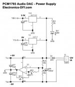
The problem with that is that it's just a buffered virtual ground. R10 and R26 bias the voltage, and taking a rail from between them gives you half of the 12v supply, so essentially 6v in comparison to true ground. From there, you take that rail and use it as ground, so true ground is -6v, and 12v is 6v. The problem with this arises when I try to use USB charging, which will inevitably ground the 5v ground to the chassis, meaning it would be necessary for the headphone input and output jacks to be isolated, and if I wanted to use a DAC attached to my computer for the amp, and wanted to use the amp, the DAC ground and virtual grounds would short, causing problems.
I might be interested in using a 3 or 4 layer board, but design and production of such boards is a bit expensive, and if there's a tiny problem in the design of a 4 layer board, it's difficult to quickly fix.
Edit - I found this prototyping lab that seems to have moderate prices ($10/sq in) and considering I'm going with the 'smaller is better' approach, it'll give an incentive to keep the board tiny, and the quality should be much better than self-etched boards. Plus, there's silkscreen!
Last edited:
- Status
- This old topic is closed. If you want to reopen this topic, contact a moderator using the "Report Post" button.