kinda tough when Harris was selling CFA in early '70s, unless "WAY before" was months, weeks?
Walt Jung's History chapter in his (free, online) Op Amp Applications tome is worth reading
Google turns up a 1972 ref to HA2500 second source
many cirucit topologies were implemented in potted modules, hybrid circuits before semi processes allowed fully monolithic impelementaitons
We arent on the same page.... differential inputs are not the same as [complimentary] push-pull input. Though in same family, I suppose.
I assume a patent search did not show up such prior 'art'. But never-the-less, I was doing similar work on my own and do not take any credit for the patent nor knew any of the inventors. Only talked to one of them when he called me after reading an article I wrote using closely related circuit as he was concerned that maybe he didnt have a patentable circuit. Maybe you meant it for other potential readers -- but i know Walt and read/have all his work since day one.
Last edited:
Yes, I always thought a differential input was absolutely necessary. This article was a jaw dropper (speaking solely for myself) because you explain how your circuit does this w/o the diff input. This and my reading of CFB op amps is starting to make much more sense now.
Full disclosure: I'm still stuck in EE101!

Full disclosure: I'm still stuck in EE101!
Last edited:

R8 could be adjusted but too much more gain and you could run into clipping the little amp. Try it first as described.
Thanks, I've not been happy with my chip amps at 6 dB using my Senn HD580 phones, but thinking it through, 12 dB should do the trick. And I have a small scope handy to verify clipping in case I decide to tweak R8.
Thanks, I've not been happy with my chip amps at 6 dB using my Senn HD580 phones, but thinking it through, 12 dB should do the trick. And I have a small scope handy to verify clipping in case I decide to tweak R8.
That was my experience too. 12dB should be fine. Tell us how it sounds.
Hi all, thanks for this very interesting discussion!
I've just received the MJE200/210, they are from Fairchild. I ordered 100 from each just to be safe and assure a good number of adequate complements. Fool of me! I have to say I could not have even one pair!!. All my MJE200 have Hfe in 140 to 170 margin while the MJE210 run between 210 to 225. I used a Peak Atlas DCA55 to classify them.
I was wondering if anybody else here would have pieces of these TRT to interchange (I would not like to buy 1000 or more just to get a good pair!!). Or any other possibility, I am open to other ideas.
Thanks in advance,
Javier
I suspect the IC manufacturers got the idea for CFA using diamond buffers topology from Jean hiraga who published the topology back in 1983 in both BJT and Jfet versions, see Le Mostre. He called it double emitter follower. The earliest patents I could find on CFA with diamond topology dates from 1985. After Jean Hirage many amplifiers appeared using the topology, Pioneer used the most tweaked or should I say advanced form of this topolgy I ve ever seen in a power amp dating from late 1980s.
Tell us how it sounds.
I'll lay out a board this weekend and go through the old etch process. It will come together in just a bit. I guarantee to put comments up.
For those just skimming through the thread, jackinnj mentioned using Dale resistors. At the minimum, I want to use these for R1 and R8. But if you haven't learned yet, the particularly good ones are as follows, best one being first.
RN6xE
RN6xC
RN6xD
where x= 0 or 5. Read the datasheet for the size dimensions..they are bigger than you might think. If I'm off base folks, please correct me. Mouser has many in stock.
RN6xE
RN6xC
RN6xD
where x= 0 or 5. Read the datasheet for the size dimensions..they are bigger than you might think. If I'm off base folks, please correct me. Mouser has many in stock.
No. Thats fine. can also put a bypass cap across the 10 ohms so the ground is low at Hf and only affective at 'hum' frequencies.
Also can try using shunt caps, as shown on pcb, withOUT lowest esr for damping, if needed.
With the headphone ground return wire going into the SGD plane wouldn't that disturb the sensitive SGD plane?
Also if you add a 10 Ohm resistor parallel with a 100nF cap you do end up with a nice SGD plane isolated from the star point which is a good thing. However, since the headphone ground return wire goes into the SGD plane it has to go through that 10 Ohm resistor before it reaches the star point. Would that not have some sort of negative effect on the headphone amplifier performance?
Expanding on that would it be ok to have a separate audio gnd star point on a powersupply PCB where the Right and Left SGD as well as the headphone gnd return wire meet and then the audio
gnd star point is separated from the main/regulator gnd star by 10R parallel with 100nF
gnd star point is separated from the main/regulator gnd star by 10R parallel with 100nF
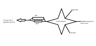
I thought that was what he has been saying all along? No? I took it pretty much the way you just drew it up..that there is the separate signal ground plane area (sig in, sig out grounds) with the parallel C and R between sig ground , tied to main star ground. I wouldn't put the signal star point on the psu board, but that's just a hunch on my part.
Last edited:
I thought that was what he has been saying all along? No? I took it pretty much the way you just drew it up..that there is the separate signal ground plane area (sig in, sig out grounds) with the parallel C and R between sig ground , tied to main star ground. I wouldn't put the signal star point on the psu board, but that's just a hunch on my part.
Yes, that was what he was saying but I am a little worried that having signal ground and headphone ground return wire sharing the same audio ground would create some issues due to the currents through the headphone ground return wire.
Also having the headphone ground return wire going through a 10 Ohm resistor is something I am a little nervous about.
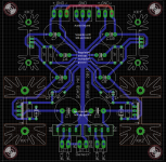
Attached is my supply.
The top left and right 3-pin Molex connectors are for supplying each amplifier board, Power ground from each board goes to the regulator/cap multiplier ground in the middle of the board.
The middle 3-pin Molex connector goes to my audio ground where SGD from each amplifer board as well as the headphone ground return wire meet. My idea was to separate this audio ground from the regulator/cap multiplier ground by 10R parallel with 100nF.
At the bottom I have my third ground, the rectifiers and first caps before the regulators are attached to this ground.
Attachments
What you end up doing is having your headamp driving your headphones as well at the 10 Ohm resistor. You lose a little voltage across it for one and it might have a few other side effects, although I'm not certain what they could be.
Some clarification would be much appreciated.
Some clarification would be much appreciated.
someone will come along and give a better and more thoughtful answer...but this is how I see it.
That 10 ohm resistor "lifts" the sig ground above the power ground. Noise, if given the opportunity, will go 'downhill'. So as I see it, any noise generated in the audio ground flows downhill to the main star point. And any noise in the psu ground will not flow 'up' into sig ground.
I ran a calc just the other day. A 1V signal with a 12dB gain comes out to 4V. To me, if you lose a volt or two, that is significant. What you're stating doesn't sound right to me. But again, a better statesman should hopefully come and clear things up.
I use the ground 'planes' mostly as shields... not as convenient connections for picking up I/O signal commons and power grounds. The current loops will not pass thru any common signal between the input, output or power. Its harder to know if this is happening when using a ground plane to attach each of the seperate commons to it.... it can be done but carefully.
Does that make sense?
Does that make sense?
Last edited:
I use the ground 'planes' mostly as shields... not as convenient connections for picking up signal commons and power grounds. The current loops will not pass thru any common signal between the input, output or power. Its harder to know if this is happening when using a ground plane to attach each of the seperate commons to it.... it can be done but carefully.
Does that make sense?
On the boards I made, this was explicitly designed in -- with the option of connecting the "shield" nearer the input or output.
- Home
- Amplifiers
- Headphone Systems
- Marsh headphone amp from Linear Audio