Hi John! I see you are back (?) in Berkeley land. I have been up in the foothills of the Sierra's - a stones throw from Nelson Pass - for the past 15 years. Cool, CA. Its a nice drive... come up and visit me.Go for it, Dick!
Last edited:
seperating power ground from signal ground on the pcb
Here is an example of what I generally do -- I use two pcb ground plans: I have a seperate power ground on opposite pcb sides of +/- traces that form a strip-line for low z distribution. It never goes over signal traces and has a seperate path to the power source ground point.
The signal shield/ground is only over the signal area/wiring. Never crosses over power wires/traces or signal ground plane areas.
Separated power and signal returns are an important part of the high-end pcb design. This keeps power filtered transient currents/ripple/rfi et al out of the signal paths (via common). Result? Greater sonic clarity and seperation. -RNM
Last edited:
Dual grnd planes
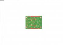
example using old pcb circuit - green color are the two seperate ground planes: signal and power.
right side is power and left or center is signal. Traces are above the ground planes in red. -RNM
example using old pcb circuit - green color are the two seperate ground planes: signal and power.
right side is power and left or center is signal. Traces are above the ground planes in red. -RNM
Attachments
Last edited:

Thanks Mr. Marsh, that is a great (though not a new one as you say!) rule to start dealing with ground. In my old days of circuits designer I had to deal with some very tough ground issues and keeping both power and signal GNDs well isolated and controlled in PCB routing was very helpful indeed. The magic rule is to avoid power ground current to interfere with signal ground as much as possible.
Another good rule is forgetting about the "magic" theoretical GND that could deal with everything with zero impedance! Always try imagine current paths in GND (following the least impedance route) to come back to source point and, in case you observe a conflict and/or interference with weak signals, try other route to avoid it.
Well we could continue with this issue for a long time but I think is better to point out that there are some very helpful resources for those interested. A good starting point may be:
- "Staying Well Grounded" H. Zumbahlen - Analog Dialog 2012-06 (Analog Devices Inc)
Here you can find a good deal of information and, what is even more important, a very helpful list of references on the Grounding subject.
Javier
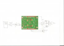
One ground plane -- the Node "0" routing is shown in cyan and can be attached to the ground plane (which would make the copper pour "cyan").
I have a couple of prototype boards to dispense of, free for the shipping -- all soldered up etc., etc. Anyone interested drop me a PM.
An externally hosted image should be here but it was not working when we last tested it.
I have a couple of prototype boards to dispense of, free for the shipping -- all soldered up etc., etc. Anyone interested drop me a PM.
example using old pcb circuit - green color are the two seperate ground planes: signal and power.
right side is power and left or center is signal. Traces are above the ground planes in red. -RNM
Where does the signal ground plane connect to the power ground plane?
Anything objectionable about this:
An externally hosted image should be here but it was not working when we last tested it.
dual mono floating PS, "balanced" 4-wire output cable is always better, resolving "gnd" between SE signal gnd, output/return gnd and PS CT is simpler when the source/signal gnd is the only common connection
but for simple headphone amps with SE source, TRS output connector these gnds are always wired together between the R,L channel boards at input and output
the xfmr CT is a "dirty" wire - large discontinuous pluses of current are present here and in the reservoir cap gnd leads - "star" these together but use a separate clean gnd return branch to the Vreg gnd ref, continuing on to the amp PS gnd in a separate "clean gnd star"
at typical headphone currents "gnd contamination" from R,L return currents mixing in common gnd system impedance is mostly ignorable due to their small size, ease of using "heavy" wiring relative to the current magnitude
I use double/reinforced insulated line xfmr, construction to allow floating output to avoid chassis safety gnd adding complication to the picture
with Class A output bias the power rails on opposite edges of the board is survivable - but is in general bad practice - will bite you with Class AB nonlinear rail currents mag fields coupling to the circuitry in between
Well, the guts and gore of it is that i use a vasly more complex arrangement that the simple one shown. The point only to not have power supply currents (ripple etal) passing thru signal common in a single-ended design. high currents are a seperate issue from headphone amp currents... but generally agree.
I use a seperate power supply (including transformers) all the way thru and seperate c.t. grounds to one point at the reg supply as you suggest. I dont want to get into grounds for all manner of circuits, here. new thread, perhaps?
I use a seperate power supply (including transformers) all the way thru and seperate c.t. grounds to one point at the reg supply as you suggest. I dont want to get into grounds for all manner of circuits, here. new thread, perhaps?
but for simple headphone amps with SE source, TRS output connector these gnds are always wired together between the R,L channel boards at input and output
at typical headphone currents "gnd contamination" from R,L return currents mixing in common gnd system impedance is mostly ignorable due to their small size, ease of using "heavy" wiring relative to the current magnitude
I dont think the above parts of your comments are a best way and wouldnt do it in a SOTA system..... everyday consumer stuff maybe OK.
I recommned volt reg be close at the signal circuitry, as well. Not in a remote area from the circuitry. But, then my circuits tend to be wideband ones and fast regulators as well.... lead inductance from PS to amp circuit can cause oscillations and poor crosstalk et al extra bypassing to poor hf/rf grounds et al. No. better for me to keep everything short as possible and for lowest Z AT the circuit. Ground Z and the various routes it can take (direct and coupled) are important for SOTA circuitry. It is one area that seperates the DIY designs and builds from the Levinson/krell/JC etc amps that a schematic doesnt show.
The high C and low L strip line for power works extreamly well in low noise, low level circuits... analog and digital. [The fields are contained mostly between the two conductors (supply line and ground) with little stray.]
Last edited:
I use a seperate power supply (including transformers) all the way thru and seperate c.t. grounds to one point at the reg supply as you suggest. I dont want to get into grounds for all manner of circuits, here. new thread, perhaps?
You have my vote for your thoughts on grounding.

EM, circuit physics isn't a democracy, the only votes that count are solutions to Maxwell's Equations
draw the current loops - the "stipline" in the posted pcb isn't doing anything, openended stripline doesn't do anything at low audio frequencies
even properly applied stripline (terminated) doesn't "work" at audio, only truely effective at MHz - the return currents will find the path of least impedance for each frequency, at DC it "resistance" controlled
http://www.diyaudio.com/forums/anal...ch-preamplifier-part-ii-2373.html#post3049769
gives an example, by 20 kHz the proximity effect has only concetrated the "image current" under the trace by ~ "halfway" - the plane current is still spread through much of the gnd plane
the xfmr CT is a "dirty" wire - large discontinuous pluses of current are present here and in the reservoir cap gnd leads - "star" these together but use a separate clean gnd return branch to the Vreg gnd ref, continuing on to the amp PS gnd in a separate "clean gnd star"
I agree with this additional detail... sometimes I either assume the reader knows the details to impliment and deal only with the concepts as a form of short hand. Good points... thx.
I agree with this additional detail... sometimes I either assume the reader knows the details to impliment and deal only with the concepts as a form of short hand. Good points... thx.
I did not cover grounding nor power supply design in the headamp article for that audience. But for many DIY on this forum, maybe some tutorials are needed. There are many books on the sunject but here are two quickies of the grounding issue for wideband width circuits (>100KHz) and esp. for digital circuits (DAC etc):
www.cvel.clemson.edu/presentation_slides/PowerBus-decoupling.pdf
www.cvel.clemson.edu/presentation_slides/automotive-circuit-board-layout.pfd
www.cci-msc.com/rigidbus/pdf/rigidbus.pdf
Good practical info that DIYers might want to read up more on it for their particular project -whatever it is.
Plenty of books on the subject exist as well. Proper grounding is important for best audio performance and sound and for trouble free projects.
only 1-2 slides mention <100 kHz - which I think is the 1st order of concern for audio electronics layout, wiring - "down there" plane partitioning, slots, moats do work - if you want to control the current paths you have to do it with conductor geometry, explicit pwr return routing - can't rely on proximity effect, image currents in planes - Resistance matters
the laminated bus rails do look like good possibilities at PA levels but I've not used them yet - DIY with Kapton and Cu roof flashing or sheet/bus bar stock?
(I have professionally designed Industrial Instrumentation for >2 decades - including strain gage instrumentaiton with Ethernet, USB 2, 100 MHz processors, DSP within inches of Av 4000 amplifiers, 16-20 bit ADC)
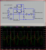
I worked up this simple sim for the xfmr CT current - some have scoffed, use faulty reasoning about circuit symmetry to claim the CT is "clean"
load on PS rails simulated with Isources - Class A bias conditions
busy plot but shows how a load frequency differing from line multiple can give large CT currents as each polarity supply cap is unevenly discharged/recharged
look at the Red R-ct trace spikes, C1,2 currents
but these nonlinear pulse contaminated currents sum to the mostly linear load current
the R2 current is equal to the (inverse) load current - is as linear as your load's impedance - can be very good for headphones
the laminated bus rails do look like good possibilities at PA levels but I've not used them yet - DIY with Kapton and Cu roof flashing or sheet/bus bar stock?
(I have professionally designed Industrial Instrumentation for >2 decades - including strain gage instrumentaiton with Ethernet, USB 2, 100 MHz processors, DSP within inches of Av 4000 amplifiers, 16-20 bit ADC)
I worked up this simple sim for the xfmr CT current - some have scoffed, use faulty reasoning about circuit symmetry to claim the CT is "clean"
load on PS rails simulated with Isources - Class A bias conditions
busy plot but shows how a load frequency differing from line multiple can give large CT currents as each polarity supply cap is unevenly discharged/recharged
look at the Red R-ct trace spikes, C1,2 currents
but these nonlinear pulse contaminated currents sum to the mostly linear load current
the R2 current is equal to the (inverse) load current - is as linear as your load's impedance - can be very good for headphones
Attachments
Last edited:
Pure awesomeness.
Though I thought "moating" (so its a verb, who knew?) was pretty common in DAC/ADC layout design. In analog, also: RNMarsh's example above does, and, heck, my boards too!
Attachments

- Home
- Amplifiers
- Headphone Systems
- Marsh headphone amp from Linear Audio