Much food for thought in that list. At first read, it strikes me as unduly - unfairly, even - restrictive. That's not a criticism - they are your opinions based on your (considerable) experience and I respect that - just an observation. Since you say it is do-able so it must be, though I do wonder just how many circuits in the wild not designed by Richard Marsh actually pass all 11... ") Given (3) I rather suspect not many.
Given (3) I rather suspect not many.
And 4., coming from you, is somewhat ironic, no? (sorry, couldn't resist..)
Given (3) I rather suspect not many.And 4., coming from you, is somewhat ironic, no? (sorry, couldn't resist..)
Here are my own modest base requirements for a line stage (similar for power amp):
1. Open loop BW of 40KHz or more (-3dB)... 20KHz min.
2. IM and THD of less than .001% at 1v rms into 30 ohms for any frequency between 20Hz and 20KHz.
3. No coupling caps on input or output or in feedback path.
4. No use of dc servo circuits to track and correct dc offset and drift.
5. No more than 6-8 transistors (excluding power supply).
6. S/N ref 1 volt rms and without weighting of at least -130dB (input can be shorted or terminated).
7. No significant harmonics above the 2nd and 3rd.
8. Closed loop gain between 12 and 20 dBv
9. Low Zout (less than a fraction of an Ohm at any audio freq).
10. Distortion not be changed by source Z.
11. Transistors should be low cost and not be exotic, hard to obtain, very expensive or no longer manufactured.
There might be a thing or two I missed, off the top of my head, but this is do-able and should be done in all audio circuits IMHO. -RNM
Do we a get a prize to post such a circuit ??
4. No use of dc servo circuits to track and correct dc offset and drift.
Why not? That the circuit does not REQUIRE a DC servo is commendable, but what about zero GNFB and very low frequency DC-servo?
I'm definitely gonna compare your amp with such a circuit.
8. Closed loop gain between 12 and 20 dBv
Can it be easily reduced? Low Z phones need 2-4x gain at best.
Much food for thought in that list. At first read, it strikes me as unduly - unfairly, even - restrictive. That's not a criticism - they are your opinions based on your (considerable) experience and I respect that - just an observation. Since you say it is do-able so it must be, though I do wonder just how many circuits in the wild not designed by Richard Marsh actually pass all 11...
And 4., coming from you, is somewhat ironic, no? (sorry, couldn't resist..)
The criteria for each of the 11 are reasonable and developed over decades but not easy for DIY. This little headphone amp is about meeting the criteria. It is amazing to me that with so many transistor part numbers, there are still so few good complements -- the jFETs I used are not that great complements, either. Would like to find better substitutes.... one's that are closer match right out of the box. Better complements would lower the harmonic distortion further.
#3 should not be hard with low dc gain circuits... phono stage would be a lot harder... Good place for a dc servo. [with downloading HD masters makes LP's a wee bit out of the party for me]
#4.... it was a solution to one person's circuit problem that got away from itself. It's downside is that designers feel they dont have to pay attention to dc drift/offset issues anymore.... just throw a servo on it. In many cases, that could be OK..... but not always. It didnt help MultiCap sales, either.
But, you got to do what is needed.... It isnt always about money.... at least not for me.
Last edited:
Hi RJM
Current conveyor
Look at Jan Didden's Pax amplifier for a very clever application.
Current conveyor
forr - I hadn't heard the term before, but on searching, it certainly seems to be a variant thereof.
Look at Jan Didden's Pax amplifier for a very clever application.
Can it be easily reduced? Low Z phones need 2-4x gain at best.
Sure, why not?
It is amazing to me that with so many transistor part numbers, there are still so few good complements -- the jFETs I used are not that great complements, either. Would like to find better substitutes.... one's that are closer match right out of the box. Better complements would lower the harmonic distortion further.
Currently the only option for close matching is to use monolithic dual jfets of a single polarity, such as LSK389, which are in production.
I hope jackinnj will offer matched input jfets for your amp *wink wink*
Do we a get a prize to post such a circuit ??
Nah, I have those already, a bottle of Glenlivet XXV 25 year old Single Malt Whisky would be nice.
Nah, I have those already, a bottle of Glenlivet XXV 25 year old Single Malt Whisky would be nice.
Rats! All out of that one from my arsenal. I'll have to restock. But. If you dont come up with a working, different topology in, say, a week, then I'll take same type but from Rosebank (1979 - last year in production - Scotland).
Currently the only option for close matching is to use monolithic dual jfets of a single polarity, such as LSK389, which are in production.
QUOTE]
I have a few of the LSK389. Need the complements that really are good complements.
Rats! All out of that one from my arsenal. I'll have to restock. But. If you dont come up with a working, different topology in, say, a week, then I'll take same type but from Rosebank (1979 - last year in production - Scotland).
Why does it have to be a different topology, the prerequisite of no caps or servo would automatically make me think of the 80s type french circuit with obvious use of Jfets. I would obviously start there and try to reduce the circuit to two stages. The french circuit is the same circuit overall than the JLH except for the use of Jfets anyway.
 Ive just thought of a way to get rid of the two caps in JLH circuit although it will probably worsen noise figure, this is one parameter your H amp cant come close to the performance of JLH though. Ill just have to check the THD figures first but I can see them being same as original circuit.
Attachments
I should have sent a note out with the PCB's I had made up. The Node "0", traces are cruciform, connecting the input, output and electrolytic grounds together. I provisioned that the copper pour could be attached to Node "0" nearer the input, nearer the output, or to the chassis.
Mine are humming along quite nicely with separate LT1963A/LT3015 Regulators for each channel.
Mine are humming along quite nicely with separate LT1963A/LT3015 Regulators for each channel.
An externally hosted image should be here but it was not working when we last tested it.
Currently the only option for close matching is to use monolithic dual jfets of a single polarity, such as LSK389, which are in production.
I have a few of the LSK389. Need the complements that really are good complements.
I meant to use a single differential, like done here:
PRE4 N-JFET preamplifier
I dont see any point to using same topology but different transistors. Its the topology that allows such excellent performance and is the best basic topology I've found for audio... IMHO. You can optimize it for low noise, better psrr, high voltage, cascoding, rf and all the rest. This one was for headphone amp but also to try the second part of the article on auto EQ of headphones which is even more audible. -RNMWhy does it have to be a different topology, the prerequisite of no caps or servo would automatically make me think of the 80s type french circuit with obvious use of Jfets. I would obviously start there and try to reduce the circuit to two stages. The french circuit is the same circuit overall than the JLH except for the use of Jfets anyway.
Last edited:
I meant to use a single differential, like done here:
PRE4 N-JFET preamplifier
very nice and a possible contender -- schematic somewhere?
I should have sent a note out with the PCB's I had made up. The Node "0", traces are cruciform, connecting the input, output and electrolytic grounds together. I provisioned that the copper pour could be attached to Node "0" nearer the input, nearer the output, or to the chassis.
Mine are humming along quite nicely with separate LT1963A/LT3015 Regulators for each channel.
An externally hosted image should be here but it was not working when we last tested it.
Hi Jack, could you please elaborate a bit more about this? When is the hum appearing, when no connection done or when connecting and, in this late case, in which of the three possibilities?
Your advice is to connect on both points as in the attached photo?
Thanks for your advice and great work with PCS's
Javier
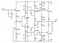
Well, I know I'm not going to win the Glenlivet bottle, nevertheless this simple CFA almost meets Richard's requirements. Beware: I'm talking about simmed figures (with Cordell's models) - still have to try it to see if it works that well even with real components.
1. about 60 dB loop gain up to 20 kHz or so
2. 0.0013% THD from 20 Hz up to 20 kHz @ 1 Vrms into 30 ohm
3. only a couple of bootstrap caps, and another couple to bypass transimpedance emitters stage (needed to keep OLG high)
4. DC offset and drift good (although not amazing) even with pure DC coupling and no servo
5. Aargh! 10 active components...
6. about -110 dB of S/N ref 1 Vrms out - could probably be improved employing low noise BJTs
7. harmonics above 3rd are < -140 dBc @ 1 Vrms into 30 ohm
8. closed loop gain 12 dB
9. Zout < 10 milliohm (approx)
10 . so it seems
11. ultra low cost parts, and quite easy to obtain
Needs further development, but it seems promising (and it could drive low Z headphones, too...).
Ciao,
L.
1. about 60 dB loop gain up to 20 kHz or so
2. 0.0013% THD from 20 Hz up to 20 kHz @ 1 Vrms into 30 ohm
3. only a couple of bootstrap caps, and another couple to bypass transimpedance emitters stage (needed to keep OLG high)
4. DC offset and drift good (although not amazing) even with pure DC coupling and no servo
5. Aargh! 10 active components...
6. about -110 dB of S/N ref 1 Vrms out - could probably be improved employing low noise BJTs
7. harmonics above 3rd are < -140 dBc @ 1 Vrms into 30 ohm
8. closed loop gain 12 dB
9. Zout < 10 milliohm (approx)
10 . so it seems
11. ultra low cost parts, and quite easy to obtain
Needs further development, but it seems promising (and it could drive low Z headphones, too...
).Ciao,
L.
Attachments
very nice and a possible contender -- schematic somewhere?
unfortunately not public (and I dont have it).
Hi Jack, could you please elaborate a bit more about this? When is the hum appearing, when no connection done or when connecting and, in this late case, in which of the three possibilities?
Your advice is to connect on both points as in the attached photo?
Thanks for your advice and great work with PCS's
Javier
It was Joan Sutherland doing the humming last night...I only meant to use the verb "figuratively".
- Home
- Amplifiers
- Headphone Systems
- Marsh headphone amp from Linear Audio